14
Configuration Key Functions
FUNC = The new setting of the selected parameter is
stored and the next parameter is displayed
(in increasing order).
MAN = Scrolls back through the parameters without
storing the new setting.
s = Increases the setting of the selected parameter.
t = Decreases the setting of the selected parameter.
Configuration Procedure
1) Switch off power to the instrument.
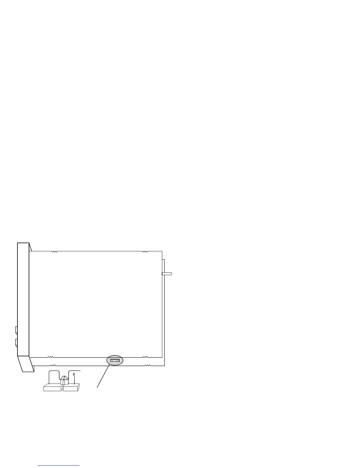
2) Remove the instrument from its case.
3) Open switch V2, located 2 inchs behind the lower
left corner of the display (see Figure 2).
4) Re-insert the instrument in its case.
5) Switch on power to the instrument.
NOTE:If instrument displays “CAL”, press the s key
to select the configuration procedure “CnF”.
6) Press the FUNC key.
V2
P1 Input type and standard range
0 = TC type L range 0 to +800.0 °C
1 = TC type J range 0 to +800 °C
2 = TC type K range 0 to +999 °C
3 = TC type N range 0 to +999 °C
4 = RTD type Pt 100 range -199 to +500 °C
5 = RTD type Pt 100 range -19.9 to +99.9 °C
6 = TC type T range 0 to +400 °C
8 = TC type L range 0 to +999 °F
9 = TC type J range 0 to +999 °F
10 = TC type K range 0 to +999 °F
11 = TC type N range 0 to +999 °F
12 = RTD type Pt 100 range -199 to +999 °F
13 = RTD type T range 0 to +752 °F
P2 Initial scale value
Not available when P1 = 5.
The initial and full scale values are used by the PID
algorithm to calculate the input span.
P3 Full scale value
Not available when P1 = 5.
The initial and full scale values are used by the PID
algorithm to calculate the input span.
NOTE: The minimum input span (P3 - P2) for:
TC = 300 °C or 600 °F
RTD= 100 °C or 200 °F.
P4 Output configuration
H = Heating.
HC = Heating/Cooling.
P5 Heating output type
rEL = Relay.
SSr = SSR.
(J305 must correspond).
 Loading...