7
WIRING GUIDELINES
Terminal board
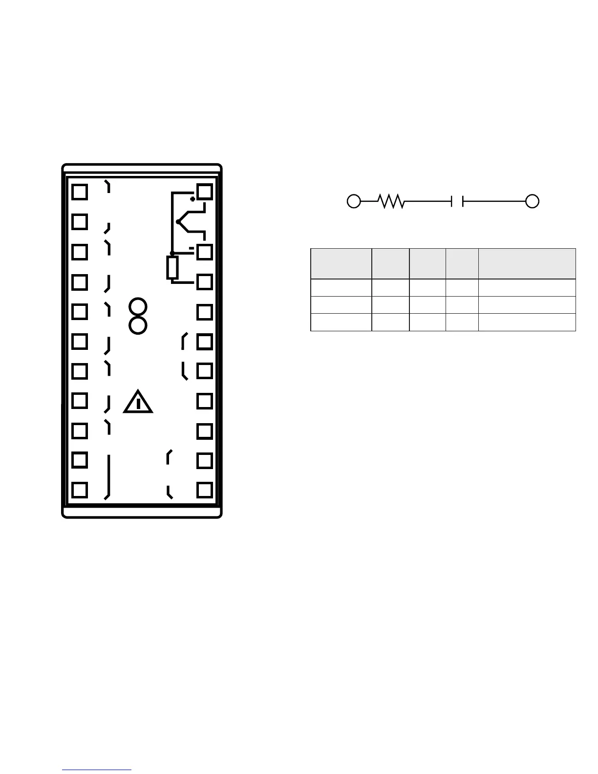
NOTE: Control outputs 1 and 2 are protected by v
aristor against an inductive load up to 0.5 Amps.
All other outputs, or external contacts in series
with the instrument outputs, need an external
snubber network (RC) across the terminals:
CR
in accordance with the following table:
daoL
tnerruC
C
)Fµ(
R
(Ω)
P
)W(
dnarotsiseR
egatloVroticapaC
Am04<740.00012/1caV062
Am051<1.0222 062caV
pmA5.0<33.0742 062caV
PWR LINE
100/240Vac
24 Vac/Vdc
12
13
15
14
AL1/C
SSR
IN-CT
16
17
18
19
21
22
11
10
9
8
7
6
5
4
3
TC
1
20
RTD
AL2/HB
RELAY
NO
C
AL1/C
RELAY
C
NO
MAIN
SSR
+
-
MAIN
RELAY
NO
NC
C
+
-