29
This completes the calibration procedure. To enter the
configuration procedure press the s key, the display will
show “CnF”. If configuration and calibration are complete,
switch the instrument off and close the switch V2 (see
configuration procedure Figure 2).
AL Current transformer minimum range value
a)Connect the calibrator and instrument as shown below.
06
07
≈
≈
b) The upper display shows “OFF”, the lower display
shows “AL”.
c)Set calibrator to 0.000 mA.
d) Press the s key; the display changes to “ON”.
e)After a few seconds, start calibration by pressing the
FUNC key. The decimal point of the least significant
digit will light to indicate the instrument is performing
the calibration. When calibration is complete, the
instrument will proceed to the next parameter.
AH Current transformer maximum range value
a)The upper display shows “OFF”, the lower display
shows “AH”.
b) Set calibrator to 50.000 mA r.m.s.
c)Press the s key; the display changes to “ON”.
d) After a few seconds, start calibration by pressing the
FUNC key. The decimal point of the least significant
digit will light to indicate the instrument is performing
the calibration. When calibration is complete, the
instrument will proceed to the current transformer
input check.
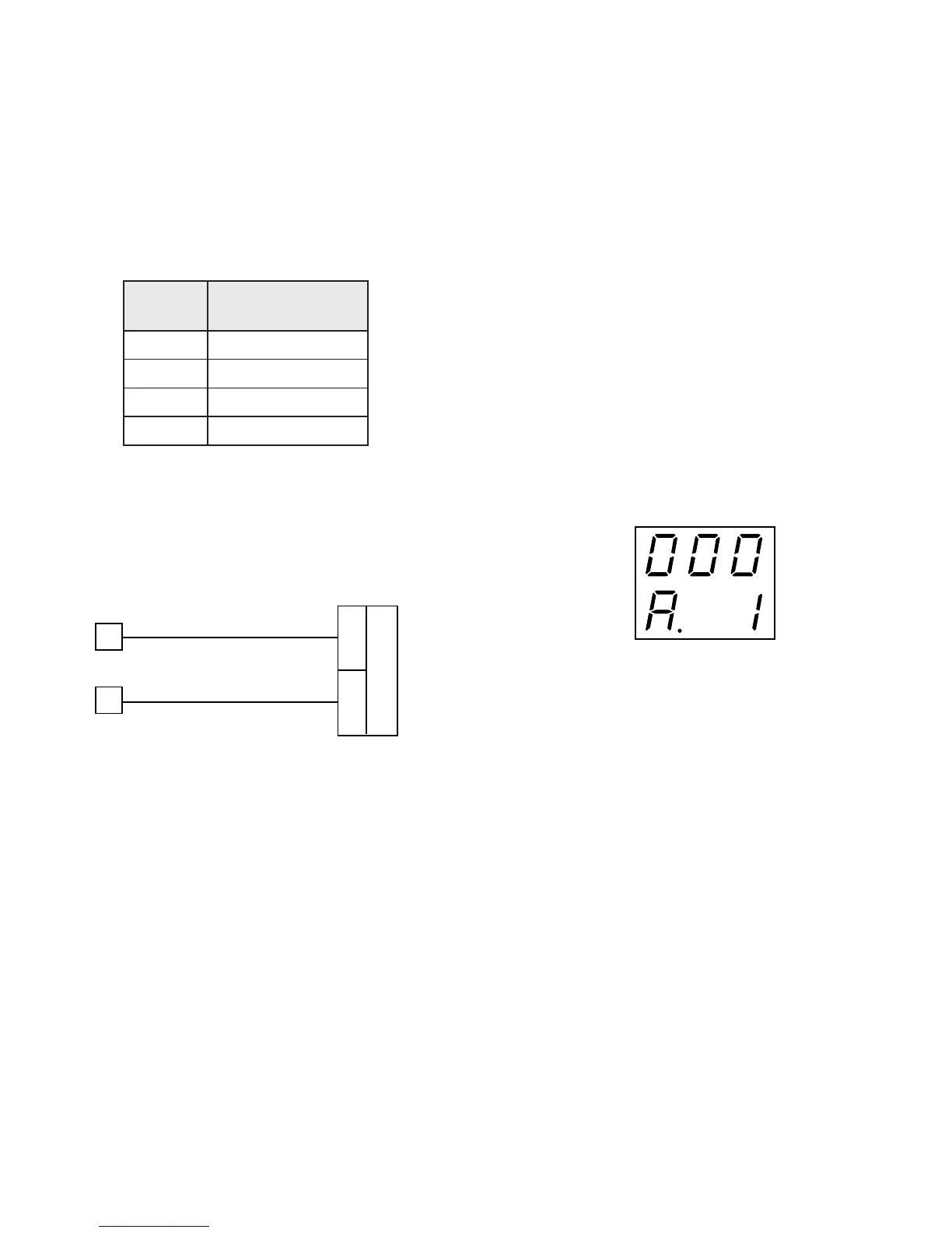
A. Current transformer input check
The display shows “A.” followed by a number showing
the measured value in counts. The calibration for “AH”
is correct if the indication is “A.01 000” ±10 counts.
a)Check the “Minimum Range” calibration by setting 0.000
mA (see parameter nAL) on the calibrator; the readout
should be “A.00 000” ±10 counts.
b) Check the linearity at half scale by setting 25.000 mA
r.m.s. on the calibrator; the readout should be “A.00
500” ±10 counts.
c)Check the “Maximum Range” calibration by setting
50.000 mA r.m.s. on the calibrator; the readout should
be “A.01 000” ±10 counts.
c) Check linearity.
NOTE:The relation between the input signal and
counts for RTD input is not linear. The correct
relation is shown in the following table:
rotsiseR
xoBxoB
xoB
xoBxoB
yalpsiD
stnuoCstnuoC
stnuoC
stnuoCstnuoC
0stnuoc01±0
001stnuoc01±35101
002stnuoc01±15102
003stnuoc01±00003
d) Press the FUNC key, the instrument will proceed to the
current transformer minimum range calibration.
 Loading...