9171100990 Rev R BE1-32R, BE1-32O/U General Information 1-5
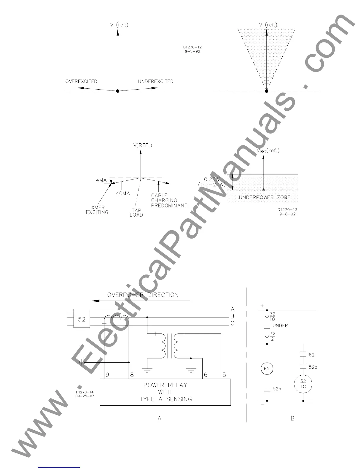
Figure 1-7. Power Factor, First and Second Quadrants
When breaker N opens, operation transfers to the third or fourth quadrants (see Figure 1-8). If
transformer exciting current predominates, operation falls in the third quadrant. If cable charging current
pre-dominates, operation falls in the fourth quadrant. In either case, the transformer losses must be
supplied. In Figure 1-8, a real current component of four milliamperes is shown and represents core
losses of the transformer (about 0.1% of rated).
Figure 1-8. Power Factor, Third and Fourth Quadrants
When breaker N opens, real power reverses from normal and flows toward the utility. This power may be
flowing to the tapped load. At this time, the relay operates and causes the 52 breaker to open.
Figure 1-9A shows an underpower tripping application based on the BE1-32O/U, model A1F with an
overpower setting of 0.5 watts and an underpower setting of 50%. The control circuit for this application is
shown in Figure 1-9B. Figure 1-8B shows the operating characteristic in the first and second quadrant.
The relay Under contact closes to trip the breaker when the real power flow from the utility drops below
0.25 watts. Because this contact is pre-closed at the instant of breaker closing, the trip circuit must be
disabled by a timing relay (62) until after the breaker has closed.
Figure 1-9. Underpower Tripping
www . ElectricalPartManuals . com