9171100990 Rev R BE1-32R, BE1-32O/U Installation 4-17
CONNECTIONS
Be sure to check the model and style number of a relay before connecting and energizing the relay.
Incorrect wiring may result in damage to the relay.
Except where noted, connections should be made with wire no smaller than 14 AWG. Relay connections
are shown in the following illustrations.
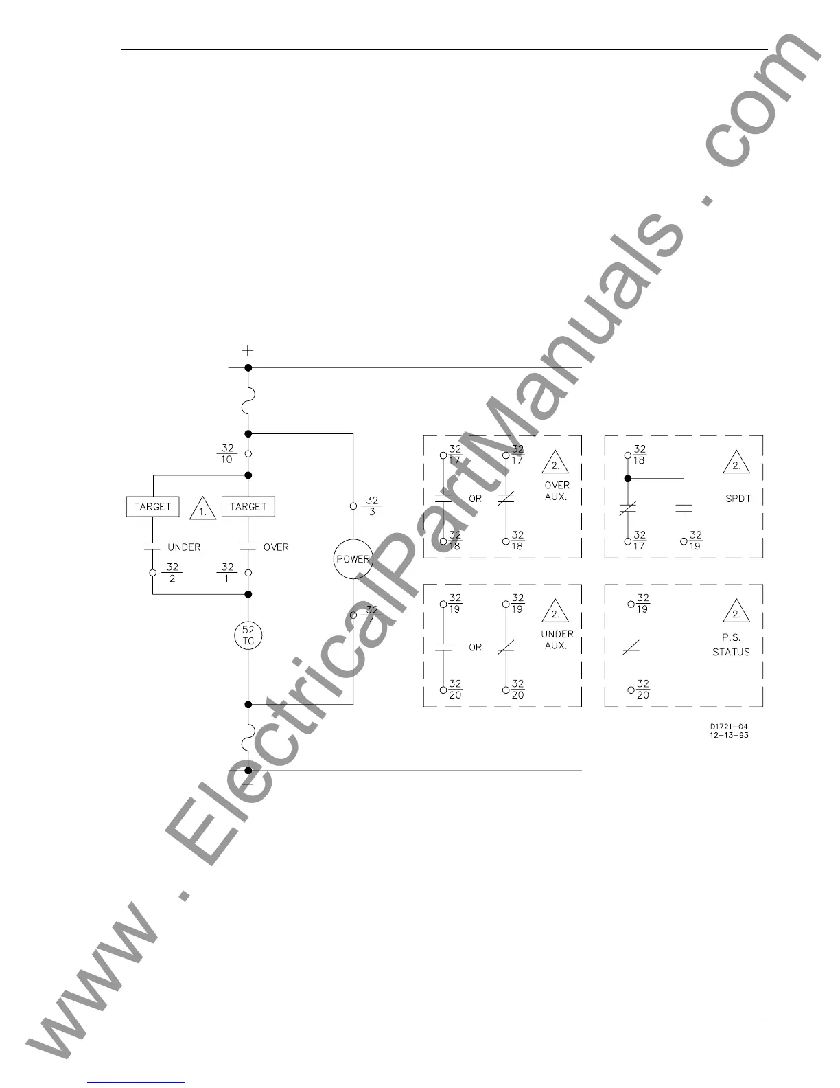
• Control circuit connections: Figure 4-16
• Internal connections: Figures 4-17 through 4-20
• Typical external connections: Figures 4-21 and 4-22
• Sensing input connections: Figures 4-23 through 4-29
Figure 4-16. Control Circuit Diagram
www . ElectricalPartManuals . com