4-22 BE1-32R, BE1-32O/U Installation 9171100990 Rev R
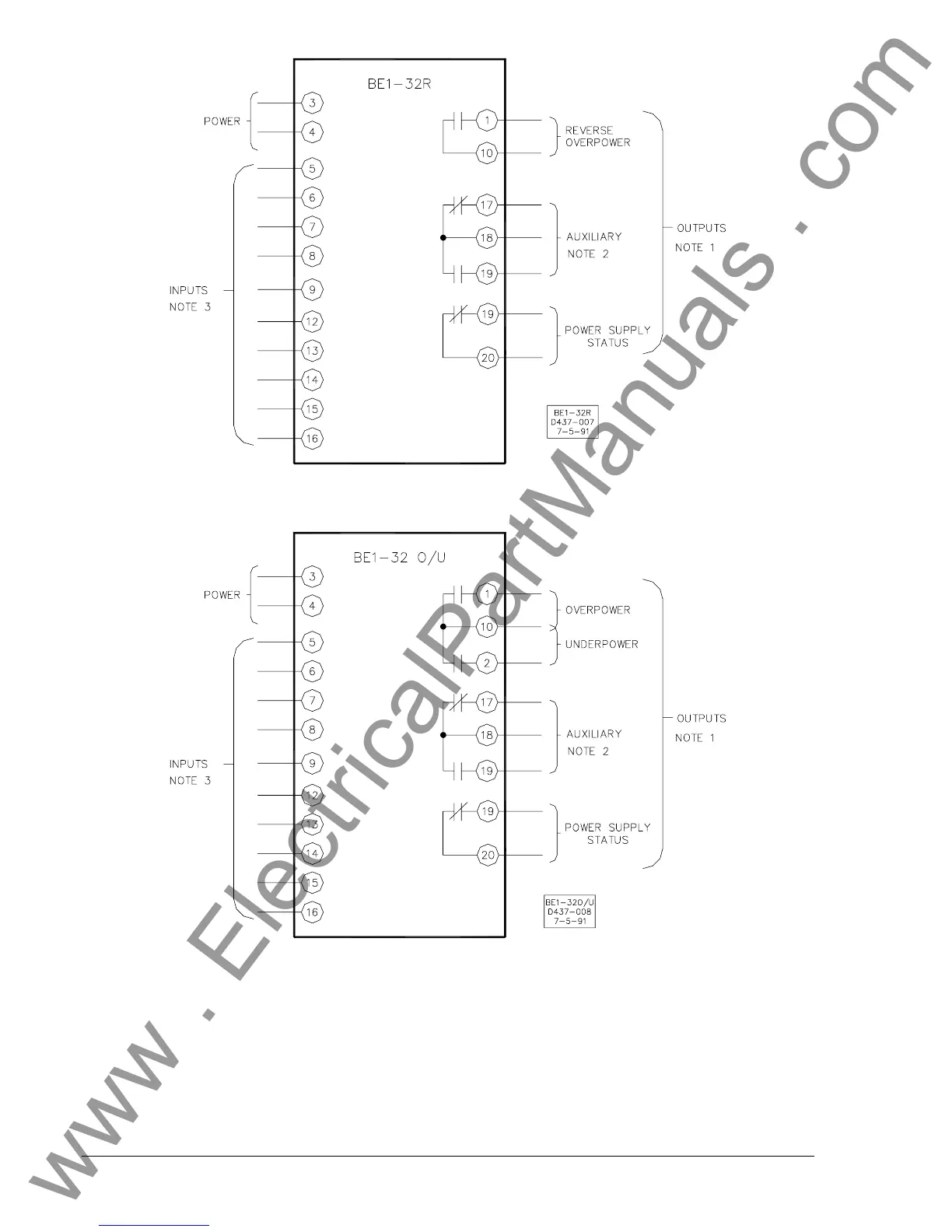
Figure 4-21. BE1-32R Typical External Connections
Figure 4-22. BE1-32O/U Typical External Connections
Notes for Figures 4-21 and 4-22
1. The overpower and underpower output contact configuration is determined by the relay style number
and may be NO or NC.
2. The auxiliary output contact configuration is determined by the relay style number and may be NO,
NC, or SPDT. If SPDT auxiliary output contacts are selected, the power supply status output is not
available.
3. The relay sensing input type determines the configuration of the sensing inputs.
www . ElectricalPartManuals . com