9287500995 Rev B 25
Power (Field) Output
The field output terminals for connection to the generator exciter field are labeled F+ and F–.
Relay Output
The common alarm relay output contact may be accessed at the terminals labeled AL1 and AL2. The
relay output is normally open.
Communication Port
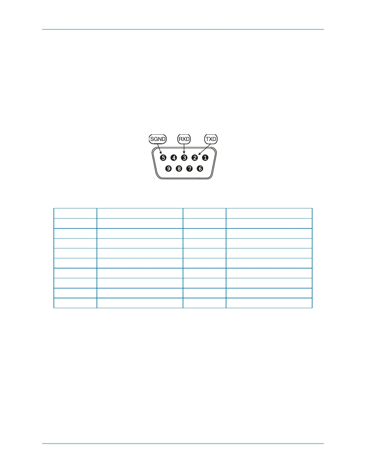
The RS-232 port on the rear panel uses a DB-9 female connector. Figure 7 illustrates the pin
assignments of the communication port and Table 17 identifies the RS-232 connector pin functions. A
standard communication cable terminated with a DB-9 male connector is used for PC or hand-held
computer interface with the BE2000E as shown in Figure 8.
Figure 7. Communication Port Pin Assignments
Table 17. Communication Port Pin Functions
BE2000E Installation