13-34 9469200995
BESTlogic™Plus DGC-2020ES
to the object(s) will change from an open to a locked state. To protect a logic document, select Protect
Logic Document from the Protection drop-down button. A password is optional.
Uploading a BESTlogicPlus File
To upload a BESTlogicPlus file to the DGC-2020ES, you must first open the file through BESTCOMSPlus
or create the file using BESTCOMSPlus. Then pull down the Communication menu and select Upload
Logic.
Downloading a BESTlogicPlus File
To download a BESTlogicPlus file from the DGC-2020ES, you must pull down the Communication menu
and select Download Logic. If the logic in your BESTCOMSPlus has changed, a dialog box will open
asking you if want to save the current logic changes. You may choose Yes or No. After you have taken
the required action to save or not save the current logic, the downloading is executed.
Printing a BESTlogicPlus File
To view a preview of the printout, click on the Print Preview icon located on the BESTlogicPlus
Programmable Logic toolbar. If you wish to print to a printer, select the printer icon in the upper left corner
of the Print Preview screen.
You may skip the print preview and go directly to print by clicking on the Printer icon on the
BESTlogicPlus Programmable Logic toolbar. A dialog box, Select Views to Print opens allowing you to
check which views you would like to print. Next, the Print dialog box opens with the typical Windows
choice to setup the properties of printer. Execute this command, as necessary, and then select Print.
A Page Setup icon is also provided on the BESTlogicPlus Programmable Logic toolbar allowing you to
select Paper Size, Paper Source, Orientation, and Margins.
Clearing the On-Screen Logic Diagram
Click on the Clear button to clear the on-screen logic diagram and start over.
BESTlogic™Plus Examples
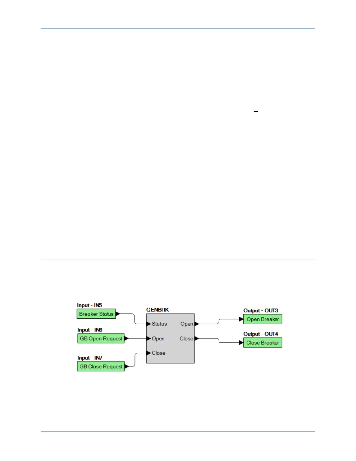
Example 1 - GENBRK Logic Block Connections
Figure 13-5 illustrates the GENBRK logic block, three input logic blocks, and two output logic blocks.
Output 3 is active while the GENBRK is sending an “open breaker” command and Output 4 is active while
the GENBRK is sending the “close breaker” command.
Figure 13-5. Example 1 – GENBRK Logic Block Connections
Example 2 - AND Gate Connections
Figure 13-6 illustrates a typical AND gate connection. In this example, Output 11 will become active when
the Low Fuel alarm AND the Low Oil Pressure alarm are true.