SECTION 3 • FUNCTIONAL DESCRIPTION
INTRODUCTION
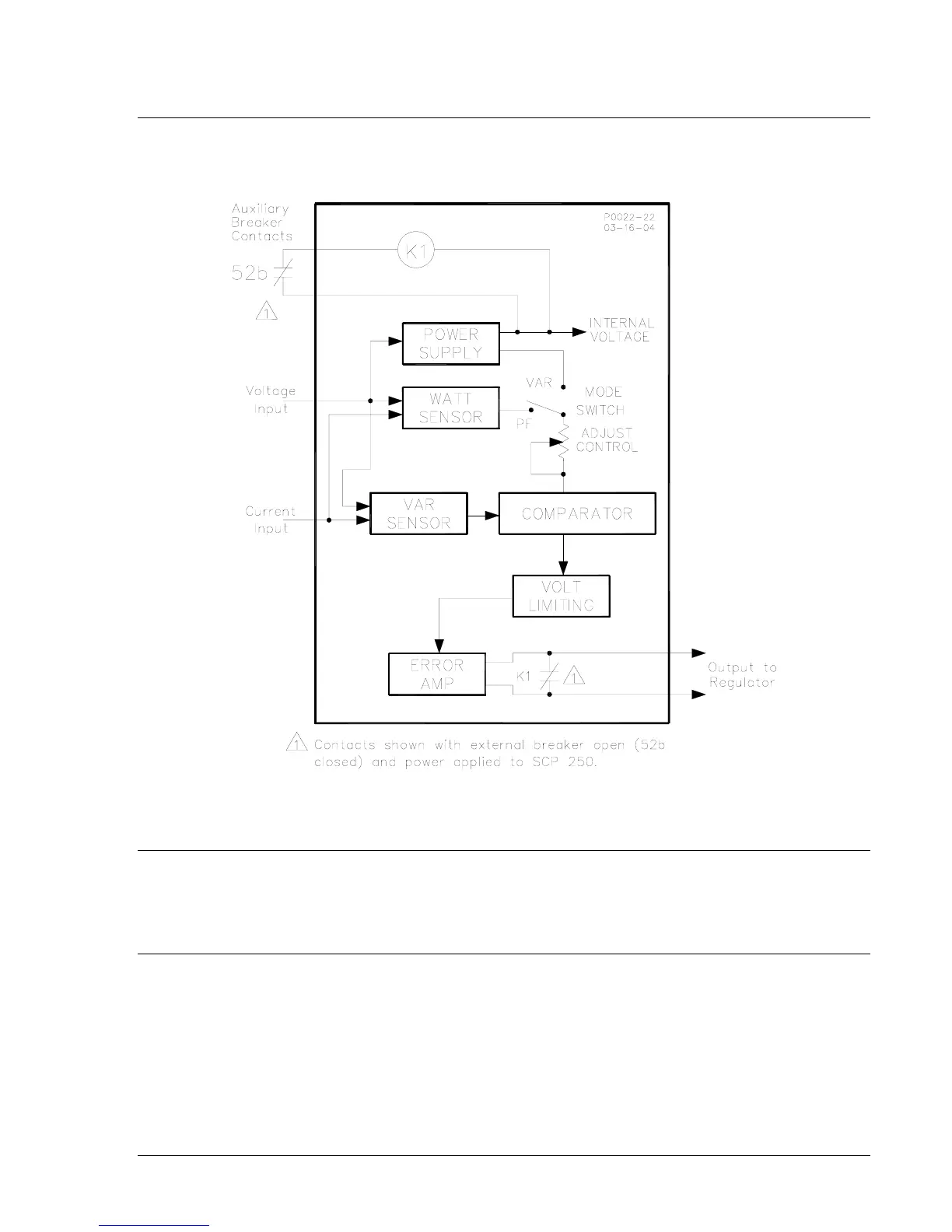
SCP 250 functions are illustrated in Figure 3-1 and described in the following paragraphs.
Figure 3-1. SCP 250 Function Block Diagram
INPUTS
The SCP 250 has two inputs: a voltage input and a current input. The SCP 250 measures the real and
reactive power based on these two inputs. The voltage input also supplies operating power to the SCP
250 power supply.
COMPARATOR AND ERROR AMPLIFIER
When var control is selected, the reactive component is compared to an adjustable dc reference and the
error signal from this comparison is amplified and supplied to the voltage regulator. As a result, the
voltage regulator (or static exciter regulator) changes its output until the programmed reactive load current
is attained.
When power factor control is selected, the reactive component is compared with an adjustable sample of
the real power component, which serves as a reference. The error signal from this comparison is
amplified and supplied to the voltage regulator. The regulator responds by changing the excitation until
the selected power factor is attained.
911000099Y Rev T SCP 250 Functional Description 3-1