SECTION 5 • OPERATION
INTRODUCTION
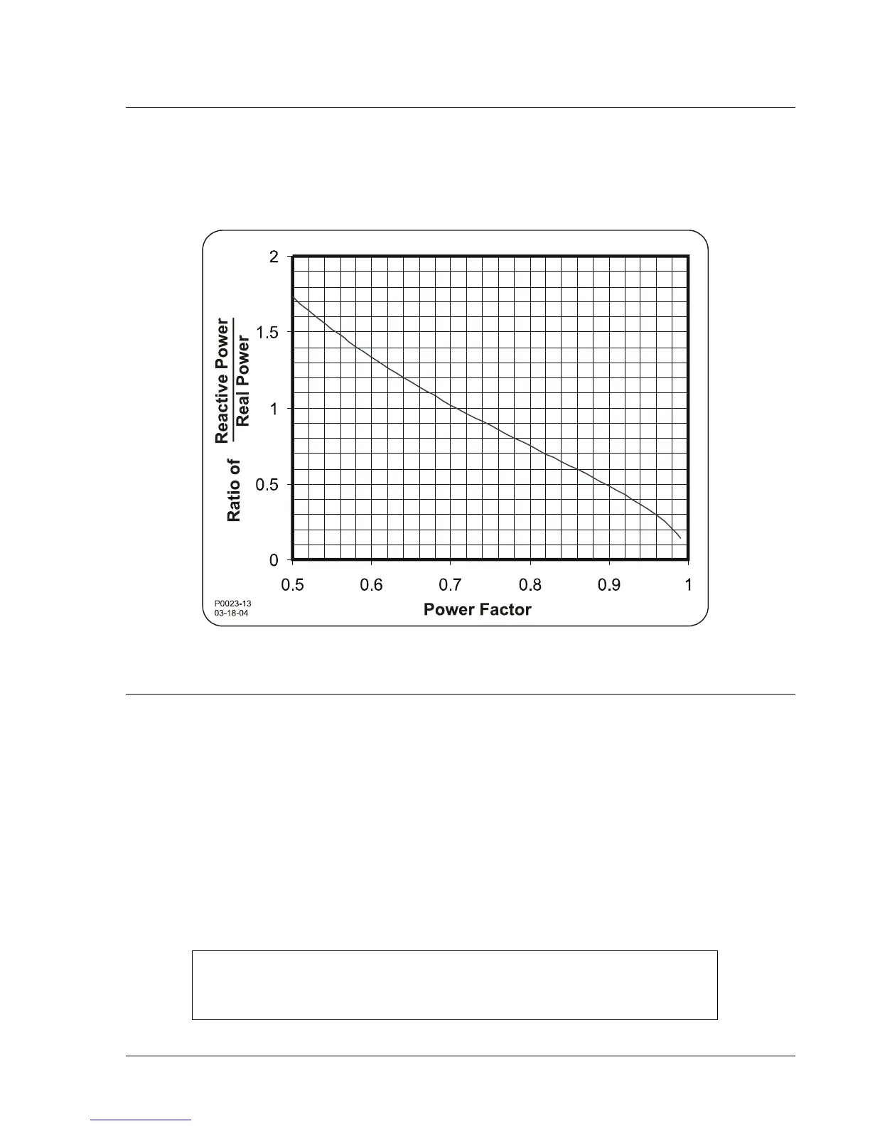
The graph of Figure 5-1 illustrates the relationship between power factor and the corresponding ratios of
reactive power to real power in an ac system. For example, in a 0.8 power factor load, reactive power is
75% of real power. This graph can be useful when adjusting the SCP 250 and evaluating system
performance. This is particularly true when a varmeter and wattmeter are available but a power factor
meter is not available.
Figure 5-1. Power Factor Relationships
GENERATOR APPLICATIONS
The following procedures contain instructions for preliminary adjustment of the SCP 250 in generator
applications.
Preliminary Adjustments for Var Control
1. Rotate the Output Limit control fully counterclockwise.
2. Place the Mode switch in the VAR position.
3. Adjust the Balance control to the midrange position.
4. Rotate the VAR Range control fully counterclockwise.
5. Connect a jumper across terminals J and K.
6. Start the generator and set its voltage at nominal with the voltage regulator’s voltage adjust control.
NOTE
With the 52 breaker open, voltage drift may be observed. This drift will disappear
when the breaker is closed in step 12.
7. Remove the jumper from terminals J and K.
911000099Y Rev T SCP 250 Operation 5-1