Crankshaft
The crankshaft has been machined with the highest
possible accuracy.
To obtain this optimal accuracy and inherent minimal
clearances, very special machines and measuring tools
are needed.
In a very sporadic case of a needed replacement of the
connecting rod, we therefore strongly recommend
replacement of a complete crankshaft.
Otherwise the accuracy can not be assured.
The little end bush in the connecting rod is made out of
bronze.
This bush can be replaced, if necessary, by a new one as
follows: Press the bush out of the connecting rod with
tool nr. 48.50.03 as shown in pict. 11.
•
Pict.
11
Press a new bush into the connecting rod with the same
tool as shown in pict. 12.
Now the oil holes have to be drilled after which the bore
of the bush has to be reamed to a diameter
,.
+ .016
12 mm.
+ .020
-*
Pict. 12
If measuring tools to check this diameter are not
available, the reaming operations has to be done in such
a way that the gudgeon pin fits in the bore freely
(Floating).
The clearance has to be .020 mm. (.00079).
Be sure that the bore of this bush is square to the
connecting rod.
In
case of a needed replacement of the crankshaft ball
bearings, these bearings first have to be extracted with
tool nr. 48.50.09 shown in pict. 13.
'J
)3
•,-•'-
i ,.-•-.,r
<
Pict. 13
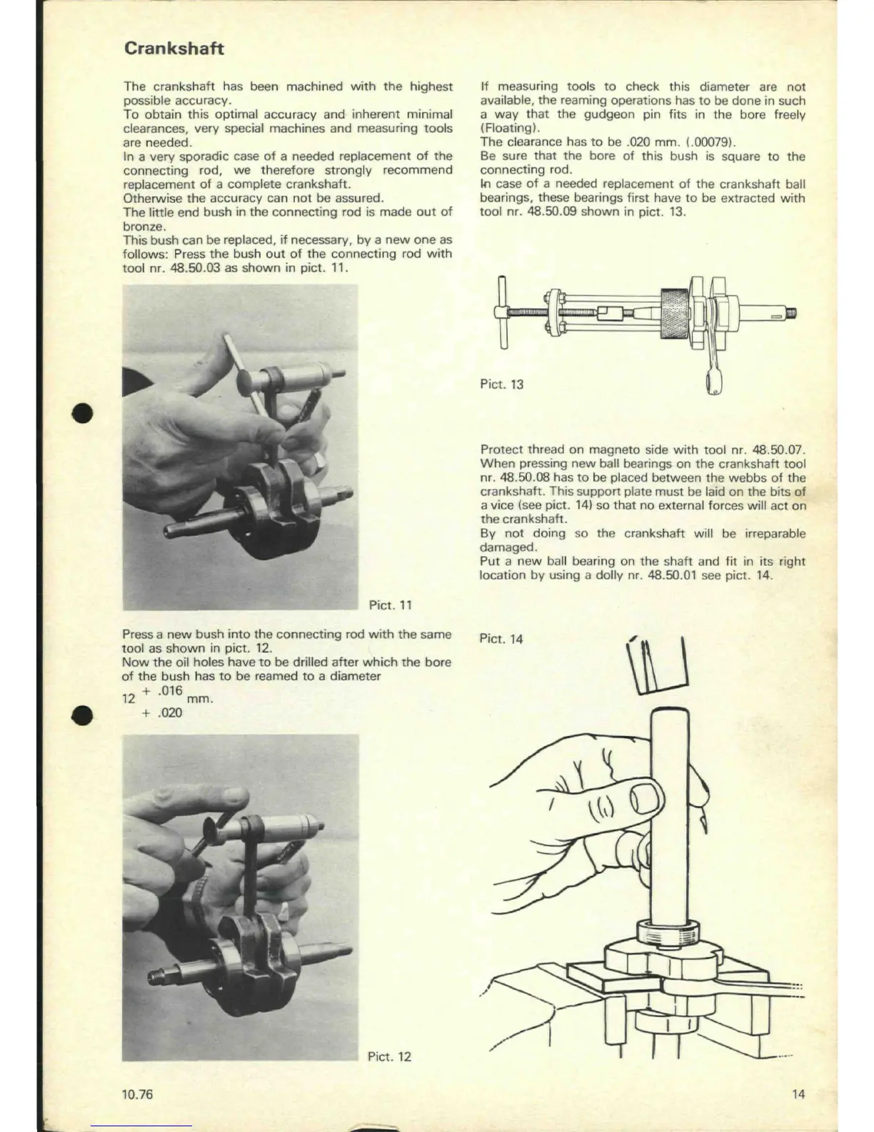
Protect thread on magneto side with tool nr. 48.50.07.
When pressing new ball bearings on the crankshaft tool
nr. 48.50.08 has to be placed between the webbs of the
crankshaft. This support plate must be laid on the bits of
a vice (see pict. 14) so that no external forces will act on
the crankshaft.
By not doing so the crankshaft will be irreparable
damaged.
Put a new ball bearing on the shaft and fit in its right
location by using a dolly nr. 48.50.01 see pict. 14.
Pict. 14
\u
\
\
I
\
5
^
!
s
T
10.76
14