Ignition 6 V - 29/5 W.
Valid for: 20
mph.
engines to nr. 772302
25 mph. engines to nr.
779301
30 mph. engines to nr. 780501
The ignition is supplied
with:
1 Coil 29 W. for the headlight
1 Coil 5 W. for additional charging of the
battery
1 H.T. coil
All these coils are mounted on the base plate, placed in
the flywheel.
When dismounting the flywheel it must be secured by
tool
nr. 48.50.10.
After removing the nut, the flywheel can be pulled off
with tool nr. 48.50.02 secured again with tool nr.
48.50.10.
Always put the flywheel with the open side upwards on
the workbench to prevent iron parts, like small washers,
to be attracted by the magnetos.
Loosen the 3 screws of the base plate and remove the
baseplate out of its position in the crankcase.
In order to move the wires freely through the rubber
grommets, oil them a little before.
Never pull the base plate to move the wires out of the
grommets but always pull the wires themselves.
Mounting the ignition the wires have to be put into the
grommets first. Some oil on the wires makes it easier.
Fit the base plate into the crankcase location, between
the cams. Take care that this is done correctly and that
no wire is pinched between base plate and casting.
Fit the 3 screws but doe not yet tighten them.
Next mount the flywheel and make sure that the key fits
in the key groove of the flywheel. Fit plain washer,
toothed washer and nut on the crankshaft.
Secure the flywheel again with tool nr. 48.50.10 and
tighten the nut.
Now turn the flywheel clockwise until the breaker gap is
maximum, visible through the holes in the flywheel.
Check the breaker gap.
The gap must be between .35 and .45 mm. (.014 and
.018").
If the gap is not correct it can be adjusted by loosening
the screw of the breakerpoint set, and moving the fixed
contact into the desired direction by means of a screw
driver.
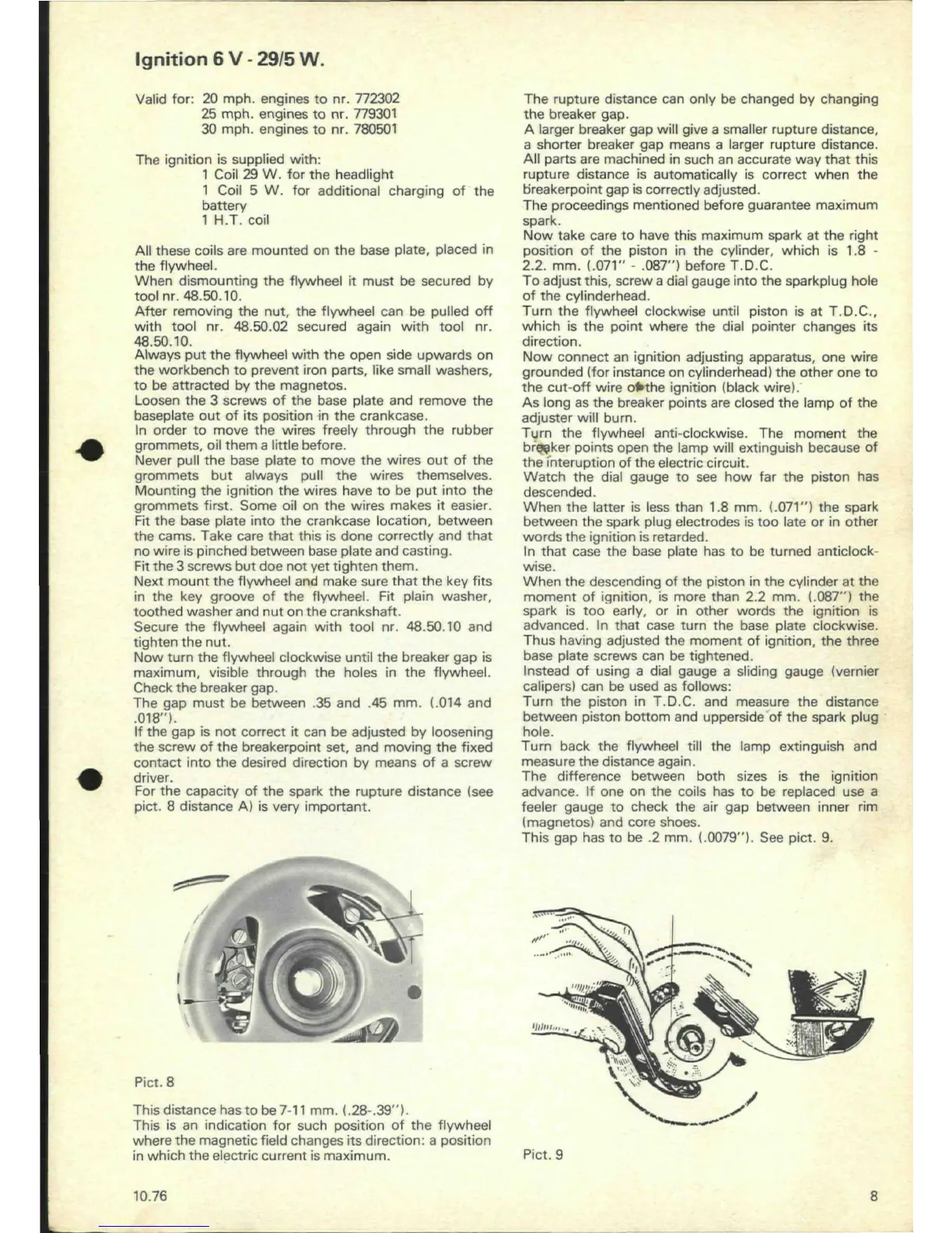
For the capacity of the spark the rupture distance (see
pict. 8 distance A) is very important.
/
:
\
Pict. 8
This distance
has
to
be
7-11
mm.
(.28.39").
This is an indication for such position of the flywheel
where the magnetic field changes its direction: a position
in which the electric current is maximum.
The rupture distance can only be changed by changing
the breaker gap.
A larger breaker gap will give a smaller rupture distance,
a shorter breaker gap means a larger rupture distance.
All parts are machined in such an accurate way that this
rupture distance is automatically is correct when the
breakerpoint gap is correctly adjusted.
The proceedings mentioned before guarantee maximum
spark.
Now take care to have this maximum spark at the right
position of the piston in the cylinder, which is 1.8 -
2.2.
mm.
(.071"
- .087") before
T.D.C.
To adjust this, screw a dial gauge into the sparkplug hole
of the cylinderhead.
Turn the flywheel clockwise until piston is at T.D.C,
which is the point where the dial pointer changes its
direction.
Now connect an ignition adjusting apparatus, one wire
grounded (for instance on cylinderhead) the other one to
the cut-off wire
ofrthe
ignition (black wire).
As long as the breaker points are closed the lamp of the
adjuster will burn.
Turn the flywheel anti-clockwise. The moment the
breaker
points open the lamp will extinguish because of
the interuption of the electric circuit.
Watch the dial gauge to see how far the piston has
descended.
When the latter is less than 1.8 mm.
(.071")
the spark
between the spark plug electrodes is too late or in other
words the ignition is retarded.
In that case the base plate has to be turned anticlock-
wise.
When the descending of the piston in the cylinder at the
moment of ignition, is more than 2.2 mm.
(.087")
the
spark is too early, or in other words the ignition is
advanced.
In that case turn the base plate clockwise.
Thus having adjusted the moment of ignition, the three
base plate screws can be tightened.
Instead of using a dial gauge a sliding gauge (vernier
calipers) can be used as follows:
Turn the piston in T.D.C. and measure the distance
between piston bottom and upperside of the spark plug
hole.
Turn back the flywheel till the lamp extinguish and
measure the distance again.
The difference between both sizes is the ignition
advance. If one on the coils has to be replaced use a
feeler gauge to check the air gap between inner rim
(magnetos) and core shoes.
This gap has to be .2 mm. (.0079"). See pict. 9.
'
!
>
V>
•m
i
limn
i
-v
s
s
Pict. 9
10.76 8
 Loading...