EasyManua.ls Logo

battioni Pagani MEC 13500 - User Manual

Default Icon
28 pages
Print Icon
To Next Page IconTo Next Page
Loading...
pag. 30
instruction manual
for use and maintenance serie MEC, STAR, AGRI
Battioni Pagani
®
INTRODUCTION
The Rotary blades vacuum pumps Battioni Pagani
®
have been designed and constructed in compliance with EEC safety regulations
and have been assessed for risks according to standard UNI EN ISO 12100:2010; in particular they are in conformity with directive
2006/42/CE and subsequent modications and additions.
Since the design of this pump complies with the denition of a machine as contained in the Machinery Directive 2006/42/EC, the
pump bears the CE mark on its identication plate. However, it must be pointed out that because of its application and the purpose
for which it is supplied, which species that it be installed by the buyer (without motive power), Battioni Pagani® refuses any and
all responsibility if the instructions in this operation and maintenance manual are not followed.
This manual contains the Declaration of CE conformity and all the instructions required by users, and by the manufacturers of plant
systems, for using our products safely. As a result, the manual must always be kept near the rotary blades vacuum pump.
The descriptions and illustrations in this manual are purely indicative.
The manufacturer reserves the right to make any type of change to this manual at any time.
GUARANTEE
At the moment of receiving the Rotary blades vacuum pump check that it is complete with all its parts.
Any anomalies or missing parts must be notied within 8 days of receipt of the product.
The Supplier guarantees that the product sold is free from defects and undertakes to repair or, by nal decision, to replace the faulty
parts only if the defects are clearly attributed to the manufacturing process or to the materials used. In any case the costs of labour,
travel and transport, and any customs expenses shall be paid by the Purchaser. The vendor is not obliged to pay damages except in
the case of fraud or grave offence. All parts subject to normal wear are excluded from the guarantee. The guarantee will cease to be
valid if:
the faults reported are the result of accidents or obvious carelessness or negligence on the part of the Purchaser,
the parts have been modied, repaired or tted by persons not authorised by the vendor,
the failures and breakages have been caused by use that is unsuitable or heavier than that provided for by the vendor,
the Purchaser has failed to make the payments as agreed by contract.
The Purchaser loses his/her right to the guarantee if he/she fails to report the defects to the vendor within 8 days of discovery,
making an exception to article 1512 of the Italian Civil Code. The Vendor reserves the right to make changes or improvements to
his/her products without being obliged to make the same changes or improvements to the units already produced and/or delivered
previously. The Vendor is not responsible for accidents or for the effects of accidents to people or property due to defective materials
and/or workmanship.
Thank you for choosing Battioni Pagani
®
.
This danger symbol in the manual means that important safety instructions are given. This information is
destined primarily for the operator whose responsibility it is not only to comply with them personally, but also
to ensure compliance by other persons exposed to the connected risks.

Table of Contents

Other manuals for battioni Pagani MEC 13500

Questions and Answers

Summary

OBLIGATORY SAFETY SIGNS

CONDITIONS AND LIMITS OF USE

INSTRUCTIONS FOR USE AND MAINTENANCE

ASSEMBLY, FITTING, INSTALLATION, DISASSEMBLY, RE-FITTING

Detailed procedures for assembling, fitting, installing, disassembling, and re-fitting the vacuum pump.

REVERSION OF DIRECTION OF ROTATION

START-UP

WORKING WITHOUT OVERPRESSURE VALVE

Specific starting procedures for MEC series pumps when no overpressure valve is installed.

DIRECTION OF ROTATION

Critical information on ensuring correct rotation direction to prevent pump damage.

SET-UP OF THE LUBRICATION SYSTEM

NORMAL LUBRICATION

Details the normal lubrication method, relying on intake phase suction for oil circulation.

OVERPRESSURE AND VACUUM ADJUSTMENT VALVES

TESTING AND RUNNING IN

START, OPERATION, STOP

TROUBLESHOOTING

MAINTENANCE AND REPAIRS

BLADES INSPECTION AND REPLACEMENT

Covers inspection methods, replacement procedures, and size specifications for pump blades.

REGULAR SERVICING

Overview

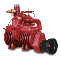
The Battioni Pagani® Rotary blades vacuum pump is a robust and versatile device designed for creating vacuum or pressure within a connected tank. It is manufactured in compliance with EEC safety regulations, including Directive 2006/42/CE and UNI EN ISO 12100:2010 standards, and bears the CE mark on its identification plate. The manufacturer emphasizes that responsibility for safe operation rests with the buyer, particularly regarding installation without motive power and adherence to the provided manual.

Function Description:

The primary function of the Rotary blades vacuum pump is to generate either a vacuum or pressure within a connected tank. This capability makes it suitable for various applications, including irrigation machines and tank cars. For specific applications, such as mixing in tank cars, a double outlet can be fitted on the manifold, allowing for both normal vacuum intake and the use of a perforated tube inside the tank for compression and mixing of loaded sewage. It is crucial to note that the pump is not designed to handle flammable and/or explosive liquids, materials, or gasses, and under no circumstances should liquids, dust, or any solid matter enter the pump, as this could lead to breakage. Safety valves are therefore essential components of any system using this pump.

Important Technical Specifications:

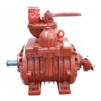
The pump is available in several versions, categorized by their power take-off and drive mechanisms. These include:

  • M/MA Version (with gearbox): Actuated through a cardan shaft at 540 r.p.m. (M) or 1000 r.p.m. (MA). Recognizable by the gearbox at the front and identification plate.
  • P Version (for pulley application): Actuated through a pulley and belts. Recognizable by a cylindrical shaft with a key and the identification plate indicating ".../P pulley application."
  • D Version (direct drive): Actuated through a cardan shaft directly connected to a splined hub. Recognizable by the splined hub at the front and the identification plate indicating ".../D direct drive."
  • H Version (for hydraulic drive): Actuated through a gears hydraulic motor. Recognizable by the hydraulic motor support at the front and the identification plate indicating ".../H hydraulic drive."
  • K/KA Version (with gearbox and hydraulic pump support): Actuated through a cardan shaft at 540 r.p.m. (K) or 1000 r.p.m. (KA) and designed to actuate a hydraulic pump of group 2 or 3. Recognizable by the hydraulic pump support and identification plate. These versions are particularly useful for tank cars where the tractor's hydraulic pump may not provide sufficient oil flow for all accessories.
  • G/GA Version (application for GARDA or LEDRA): Applied on GARDA or LEDRA groups and cannot be used independently. Recognizable by an external pinion at the front and the identification plate. GA versions operate at 1000 r.p.m.

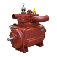
All STAR and AGRI series versions can be supplied with a back tank in cast iron or an extractable side tank in sheet metal. Each pump comes with an identification label detailing its model, serial number, production year, max relative pressure, max vacuum, max absorbed power, max r.p.m., max rate of flow, CE mark, and weight.

Operating parameters vary by model but generally include:

  • Revs M, K: 450-500 rpm (working), 600 rpm (maximum)
  • Revs P, D, H: 1000 rpm (working), 1200 rpm (maximum)
  • Revs MA, KA: 800 rpm (working), 1000 rpm (maximum)
  • Pressure: 0.5-1 bar (working), 1.5 bar (maximum)
  • Vacuum: 80% (working), 95% (maximum)
  • Outside temperature side cylinder compression: 80-90°C (working), 130°C (maximum)
  • Working time with long life blades: 6-8 min (working), 15 min (maximum)
  • Working time ballast version -0.65 bar: continuous

The maximum allowed pressure is 2.5 absolute bar (1.5 relative bar). A depression valve (set at -0.80 bar) and an overpressure valve (set at 1 bar) are essential for safe operation. Too high a vacuum can cause body ovality, waviness, or blade breakage, while excessive pressure can lead to damage.

Usage Features:

  • Installation: The pump should be assembled horizontally with feet downwards, in an easily accessible and protected position on the vehicle, with a maximum longitudinal slope of 5° relative to the horizontal plane. Connections to the tractor's P.T.O. shaft (540 r.p.m. or 1000 r.p.m. depending on version) or hydraulic motor must be made carefully, ensuring correct alignment and tension for cardan shafts or belts. For pulley applications, proper belt tension is critical to prevent sliding and reduce wear on belts and bearings.
  • Hydraulic System (for H version): The hydraulic system requires an oil tank with sufficient capacity (approximately 3 times the oil in circulation) to prevent overheating. A heat exchanger may be necessary. Lines should have a diameter at least as large as the motor/pump ports, be perfectly sealed, and as short as possible to minimize load loss. Flexible tubing is recommended to reduce vibrations. Filters are essential, with coarse filters recommended for pump intake. Only hydraulic fluid conforming to ISO/DIN standards with specified viscosity should be used, avoiding mixtures of different oils.
  • Starting Up: Before starting, all circuit connections must be exact and clean. The oil tank should be filled using a filter, and the circuit bled. Pressure relief valves should be set to the lowest possible setting. The system should be run at minimum speed for a few moments, bled again, and the oil level checked. Gradual heating of the system is achieved by rapidly switching it on and off if the temperature difference between pump/motor and fluid exceeds 10°C. Pressure and speed should then be gradually increased to pre-set operating levels.
  • Direction of Rotation: Before starting, ensure the P.T.O. shaft turns freely and the direction of rotation matches the arrow indicated on the pump. Operating the pump in the opposite direction can damage components. The direction of rotation can be reversed by disassembling and reassembling certain components, including rotating the body 180° on a horizontal level and replacing flange gaskets. For STAR or AGRI series with force feed lubrication, the same instructions as for automatic lubrication apply. For MEC series with force feed lubrication, replacing the lubrication pump is not necessary as it is bi-directional.
  • Controls: A handle on the manifold controls intake and compression phases. This operation should only be performed when the pump is not running.
  • Temperature Indicator (Thermo Tape): MEC 9000-11000-13500 versions are equipped with a thermo tape on the compression side. A reversible scale changes color from black to blue between 90°C and 120°C to prevent overheating. A blue square with a white dot turning black indicates temperatures exceeding 160°C, signifying incorrect use (prolonged operation at maximum vacuum) and necessitating disassembly and replacement of seals, oil seals, and blades.
  • Protective Devices: The pump must be equipped with protective devices to isolate moving parts and prevent access by operators, as well as to protect against material projection in case of heavy breakage. M/MA, K, KA, and D versions come with a CE plastic protective device for the P.T.O. shaft.

Maintenance Features:

  • Guarantee: The product is guaranteed against manufacturing defects and material faults. Labour, travel, transport, and customs expenses are borne by the purchaser. Normal wear parts are excluded. The guarantee is void if faults result from accidents, carelessness, unauthorized repairs, unsuitable use, or failure to make agreed payments. Defects must be reported within 8 days of discovery.
  • Lubrication System: Three types of lubrication are available:
    • Normal Lubrication: Occurs only during the intake phase, with oil sucked from the tank by vacuum. Compression phase lubrication uses residual oil. Available for MEC 1000 and MEC 1600.
    • Forced Lubrication: Occurs during both intake and compression phases via a gear pump actuated by the rotor shaft. The pump sends oil to a manually adjusted metering tap, with excess oil returning to the tank. Standard for MEC, STAR, AGRI models.
    • Automatic Lubrication: Occurs during both intake and compression phases via a piston metering pump with adjustable flow rate, actuated by the rotor. Oil is injected directly, eliminating manual adjustment and saving oil. Available on request for MEC, STAR, AGRI models.
  • Oil Type: Only new mineral oil meeting ISO VG 100 (SAE 30) or "Battioni Pagani vacuum pump oil" should be used for internal lubrication. Absolutely avoid transmission oil, used oil, hydraulic oil, vegetable oil, gear oil, or brake fluid. Gearbox oil (for M-MA-K-KA versions) should be ISO VG 460.
  • Oil Level: Check oil level regularly. For MEC series, the minimum is indicated by a notch on the level rod; maximum is when the tank is full. For STAR/V, AGRI/V series, the minimum is the total length of the plug with level rod; maximum is a full tank. For STAR/F, AGRI/F series, the minimum is the lower notch on the indicator on the external tank; maximum is a full tank.
  • Oil Quantity: When running, check that the oil quantity dripping from the regulator tap matches the specified values for Forced and Automatic Lubrication. Add only unused clean oil. For M-MA-K-KA versions, the first gearbox oil change is after approximately 100 working hours, and subsequent changes every 300 working hours.
  • Cleaning:
    • Body: If sewage enters, wash immediately by sucking in diesel or fuel oil during the compression phase, then oil. This procedure should also be followed if the pump will be inactive for a long time. Disconnect suction/delivery tubes and seal the manifold cover to prevent rust. Do not use water. If disassembled, a preliminary wash with detergents (e.g., thinners) is advisable.
    • Oil Tank: Wash at least once a year using solvents after removing the manifold.
    • Valves: Wash and clean valves at least once a month with water or non-corrosive detergents after removal.
  • Checks:
    • Valves: Regularly check that all overflow and pressure/vacuum valves are working efficiently.
    • Blades: Inspect for wear by removing the inspection plug, rotating the rotor to align a blade with the inspection hole, and comparing its height to the reference ring. Replace the entire set of blades if the height is less than the reference ring. Blades are made of standard material (for no-strong, infrequent uses) or special material (for strong, frequent uses and thick sewages, offering excellent resistance to wear, mechanical, and thermal stress). Common causes of blade damage include heat, lack of lubrication, sewage entry, high pressure/vacuum, and rust from prolonged inactivity.
  • Replacement of Rubber Ball: Unscrew and raise the valve-holder cover (AGRI/STAR) or manifold (MEC), replace the rubber ball, and re-fit.
  • Replacement of Gears (M/MA/K/KA versions): Unscrew gearbox cover screws, use extraction screws to remove the cover, take out the gear with a splined shaft using an extractor, unscrew the self-locking nut for the pinion, and use an extractor.
  • Regular Servicing:
    • Check oil circulation: Inspect sight glasses daily.
    • Check oil level in tank: Use the oil level on the outside of the tank weekly.
    • Check wear of blades: Remove threaded plug every 300 working hours.
    • Check over-pressure and vacuum regulator valves: Once a week.
    • Wash oil tank: Once a year.
    • Wash body internally: Put in oil + diesel oil (after washing, lubricate with oil only) whenever sewage enters or when inactive for a long time.
    • Wash lubrication pump: Use a brush and compressed air once a year or for prolonged inactivity.
    • Check overflow valves: Once a month.
    • Lubricate P.T.O. (M/MA/K/KA/D versions): Oil with a brush and lubricating oil once a month.
    • Wash and clean valves: Once a month.
  • Putting Out of Service and Demolition: Before demolition, separate lubricating oil, rubber/plastic parts, and cast iron/steel parts for correct disposal. Do not discard the pump in the environment. Use specialized treatment services for lubricating oil disposal.

battioni Pagani MEC 13500 Specifications

General IconGeneral
Brandbattioni Pagani
ModelMEC 13500
CategoryWater Pump
LanguageEnglish

Related product manuals