Page 12 >"-&#$95<19)(&?2$+#1"<+@&,($)+$&9)((&ABCCCBCDDBEFGF/ Item 57608
HI>;JK LM;NIJOL! PIO!J;!I!Q;H;JRM
H$##1<8&)<*&J$+#1<8
JL&MN;0;!J&H;NOLRH&O!jRNK&>NLP&IQQOV;!JIU&LM;NIJOL!%&
P)X$&+2-$)#$&J-188$-&1+&1<$&"77B,"+1#1"<&)<*&2<,(28$&#""(&7-":&1#+&
$($9#-19)(&"2#($#&4$7"-$&,$-7"-:1<8&)<.&,-"9$*2-$&1<3+&+$9#1"</
I*]2+#1<8$&P1#$-&I<8($
A miter cut is one that is at an angle across the
horizontal surface of the material. 45º miter
cuts to join two pieces in a right angle corner
are common. A 30º cut is often used for a
scarf joint or to make a chamfered end.
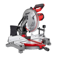
1. Loosen the Miter Lock Knob by turning it
counterclockwise to unlock the Miter Table.
Push down on the Miter Detent Lock Lever
and move the Table to the desired angle.
2. The Miter Angle Indicator will indicate the selected
angle. When the Miter Detent Lock Lever is
released, the Table will lock into place at often
used miter angles, including 0º, 15º, 22.5º, 30º,
31.6º, 45º and 48º left on both left and right sides.
3. To override the pre-set detents (stops) for micro
adjustments at any angle, push down and
hold the Miter Detent Lock Lever and adjust
Table to any position on the miter scale.
P1#$-&U"9X&
Y<"4
P1#$-&V$#$<#&
U"9X&U$W$-
>182-$&>
4. Tighten the Miter Lock Knob after
adjusting the miter angle.
5. With the Table adjusted to the desired angle,
place the workpiece flush against the Fence,
secure it with the Clamp and make the cut.
I*]2+#1<8$&'$W$(&I<8($
A bevel cut is one that is at an angle vertically. Bevel
cuts can be used to miter relatively wide and thin
material. Bevel cuts can be used in combination with
a miter cut to form a compound angle. Compound
angle cuts are often used in crown moldings,
picture frames and similar trim materials.
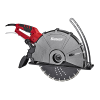
1. Loosen the Bevel Lock Knob at the rear of the
saw to unlock the Saw Head Assembly.
2. To adjust the left bevel angle between 0º and 45º,
move the Saw Head Assembly to the left to the
desired angle. Read the angle on the Bevel Scale.
3. Press the Bevel Angle Lock Button during
adjustment to also set angles up to 48° left
bevel angle or up to 3° right bevel angle.
4. Lock the Saw Head Assembly into position
by rotating the Bevel Lock Knob clockwise.
Tighten firmly but do not over-tighten.
5. Make a sample cut in a piece of scrap to
confirm that the bevel angle is correct.
If it is not, correct the angle before cutting.
SIN!O!Ti&&JL&MN;0;!J&H;NOLRH&O!jRNK%&&
I*]2+#$&H(1*1<8&>$<9$&9($)-&"7$&'()*$^+&
92##1<8&,)#5&)7#$-&:)X1<8&)<.&)*]2+#:$<#&#"$&
92##1<8&)<8($/&&P"W$$&'()*$-"285&1#+&72((&
-)<8$&"7&:"#1"<&#"&$<+2-$$&>$<9$&1+&9($)-/
'$W$(&I<8($&'$W$(&I<8($&
U"9X&'2##"<U"9X&'2##"<
'$W$(&'$W$(&
U"9X&Y<"4U"9X&Y<"4
>182-$&T
 Loading...