Page 16 >"-&#$95<19)(&?2$+#1"<+@&,($)+$&9)((&ABCCCBCDDBEFGF/ Item 57608
HI>;JK LM;NIJOL! PIO!J;!I!Q;H;JRM
Q)(14-)#1<8$&'$W$(&I<8($
For making accurate cuts, the Saw Blade must
be adjusted to be exactly vertical to the Table.
1. To check the angle, have the Saw Head
Assembly in its normal upright position and
set to the 0º bevel position. Make a cut on a
piece of flat sided, fairly thick scrap material.
2. Check the cut with an accurate square.
The cut should be at exactly 90º.
3. Angle can also be checked by rotating one cut-off
piece 180º and holding the cut ends together.
If the cut is not exactly vertical, the two
pieces will form a slight angle.
`k&'$W$(&I<8($&I*]2+#:$<#
1. First unplug the tool.
2. Set the Miter Table at 0°.
3. Loosen the Bevel Lock Knob, move the Saw Head
Assembly until the Bevel Angle Indicator is at 0° on
the Bevel Scale, then tighten the Bevel Lock Knob.
4. Pull down the Saw Head until the
Blade just enters the table insert.
5. Place a framing square on the Miter Table
and up against the Saw Blade.
!LJ;% The square must contact the surface of the
Blade, not the teeth, for an accurate reading.
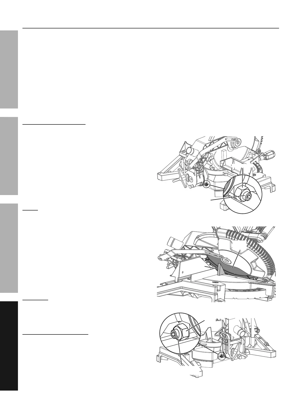
6. If the Blade is not 90° square with the Miter
Table, loosen the Bevel Lock Knob, tilt the
Saw Head completely to the left, loosen the
Lock Nut on the 0° Bevel Angle Adjustment
Bolt and adjust the Bolt in or out with a hex key
to increase or decrease the bevel angle.
7. Tilt the Saw Head back to the right at 0°
bevel and recheck for alignment.
8. After alignment is achieved, tighten the
Bevel Lock Knob and Lock Nut.
SIN!O!Ti&&JL&MN;0;!J&H;NOLRH&O!jRNK%&&
Adjust the Sliding Fence clear of the Blade′s
92##1<8&,)#5&)7#$-&:)X1<8&)<.&)*]2+#:$<#&#"$&
92##1<8&)<8($/&&P"W$$&'()*$-"285&1#+&72((&
-)<8$&"7&:"#1"<&#"&$<+2-$$&>$<9$&1+&9($)-/
eEk&'$W$(&I<8($&I*]2+#:$<#
Adjust the 45° bevel angle only after
performing the 0° bevel angle adjustment.
9. Loosen the Bevel Lock Knob,
10. Move the Saw Head to the left until the Bevel
Angle Indicator is at 45° on the Bevel Scale.
11. Pull down the Saw Head until the
Blade just enters the table insert.
12. Place a triangle square on the Miter Table
and up against the Saw Blade.
13. If the Blade is not 45° with the Miter Table, tilt
the Saw Head to the right, loosen the Lock
Nut on the 45° Bevel Angle Adjustment Bolt
and adjust the Bolt in or out with a hex key
to increase or decrease the bevel angle.
14. Tilt the Saw Head back to the left at 45°
bevel and recheck for alignment.
15. After alignment is achieved, tighten the
Bevel Lock Knob and Lock Nut.
U"9X&!2#U"9X&!2#
``° ° '$W$(&I<8($&'$W$(&I<8($&
I*]2+#:$<#&'"(#I*]2+#:$<#&'"(#
J-1)<8($&J-1)<8($&
H?2)-$H?2)-$
H)3&H)3&
'()*$'()*$
U"9X&U"9X&
!2#!2#
eEeE° ° '$W$(&I<8($&'$W$(&I<8($&
I*]2+#:$<#&'"(#I*]2+#:$<#&'"(#
 Loading...