G 120 II V
Page 16 1st Edition, Rev. 0 Chg. 2
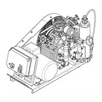
3.1.3 Air Flow Diagram
Refer to Figure 3-2. The gas is drawn in through intake connector (1), compressed to the final pressure in
cylinders (2, 3, 4,) and cooled by intercoolers (5, 6) and after cooler (7). The safety valves (8,9, 10) pro-
tect from overpressure in the individual stages. The compressed gas is purified by Inter-stage separator
(11) and oil and water separator assembly (12). The Inter-stage separator (11) and oil and water separator
(12) are drained by condensate valves (14). An Automatic Condensate Drain system is available as an
option. The pressure maintaining valve (13) ensures that pressure is built up in the HP drying system
from the start of delivery, thus achieving constant optimum drying.
Figure 3-2 Air Flow Diagram
1. Intake Manifold
2. 1st Stage Cylinder
3. 2nd Stage Cylinder
4. 3rd Stage Cylinder
5. 1st Stage Intercooler
6. 2nd Stage Intercooler
7. 3rd Stage Aftercooler
8. 1st Stage Safety Valve
9. 2nd Stage Safety Valve
10. 3rd Stage Safety Valve (Final Pressure)
11. Inter-stage Separator
12. Oil and Water Separator
13. Pressure Maintaining Valve
14. Manual Condensate Drain Valve
14
11
4
9
2
1
3
8
5
14
12
Purification
System
13
10
6
7
 Loading...