E
Evan ParkAug 7, 2025
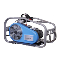
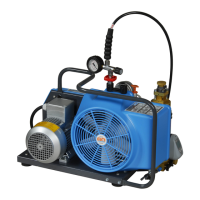
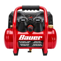
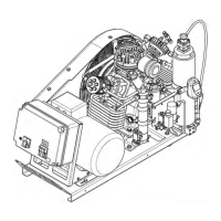
Why is my Bauer Air Compressor running too hot?
- SShannon HunterAug 7, 2025
Your Bauer Air Compressor might be running too hot due to several reasons. Check if there is an insufficient supply of cooling air, and ensure adequate ventilation. Also, the intake or outlet valve might not be closing properly, so inspect and clean the valves, replacing them if necessary. Finally, verify that the compressor's rotation direction is correct according to the arrow on the compressor.