EasyManua.ls Logo

Bauer Mini Verticus User Manual

Bauer Mini Verticus
138 pages
To Next Page IconTo Next Page
Page #1 background imageLoading...
Page #1 background image
Instruction Manual and Replacement Parts List
BAUER Compressors, Inc. Phone: (757) 855-6006
1328 Azalea Garden Road Fax: (757) 855-6224
Norfolk, Virginia 23502-1944 www.bauercomp.com
April 4, 2013 1st Edition, Rev. 0 Chg. 2 MNL-126509
© Bauer Compressors, Inc.
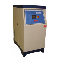
Mini Verticus
High Pressure Gas Compressor Units
G 120 II V

Table of Contents

Questions and Answers:

Bauer Mini Verticus Specifications

General IconGeneral
BrandBauer
ModelMini Verticus
CategoryAir Compressor
LanguageEnglish

Summary

Mini Verticus High Pressure Gas Compressor Units G 120 II V Instruction Manual and Replacement Parts List

CHAPTER 1: INTRODUCTION

How To Use This Manual

Guidance on navigating the manual and understanding its content.

Manual Safety Notices

Highlights important safety instructions and warnings for personnel and equipment.

How to Use the Replacement Parts List

Explains the conventions and usage of the replacement parts list section.

How to Use the Appendix

Details the content and purpose of the appendix section.

Unit Specifications

Provides technical specifications for the G 120 II V compressor unit.

Pressure Switch Settings

Details the settings for inlet and final pressure switches.

CHAPTER 2: OPERATING INSTRUCTIONS; MAPLE SYSTEM

Description

Overview of the Maple System touchscreen operator interface and its functions.

Emergency Stop Button

Function and usage of the emergency stop button for immediate shutdown.

Operator Interface

Description of the operator interface, including its screen layout and controls.

Run Screen

Details the initial screen for compressor control and monitoring.

Main Menu Screen

Explains the navigation and options available from the main menu.

Starting and Stopping Unit

Procedures for safely starting and stopping the compressor unit.

Before Starting.

Pre-operational checks required before starting the compressor.

To Start Unit.

Instructions for initiating the compressor's operation.

SCREEN FLOW

Diagram illustrating the flow between different interface screens.

CHAPTER 3: IK120 II C & G

Maintenance and Parts

Covers maintenance procedures and identification of parts for the IK120 II C & G.

Description

General description of the IK120 II C & G compressor units.

Component Location

Identifies the location of key components on the compressor block.

Air Flow Diagram

Illustrates the path of air through the compressor stages and system.

Compressor Lubrication

Details the lubrication system, oil checks, and oil change procedures.

Oil Level Check

Instructions for checking the oil level using the sight glass.

Oil Change Interval

Specifies the recommended interval for changing the compressor oil.

Oil Change

Step-by-step instructions for performing an oil change.

Inter-stage Separator

Description and maintenance of the inter-stage separator.

Valves and Heads

Information on compressor valves, heads, and their functional descriptions.

General Instructions for Changing the Valves

Guidelines and precautions for replacing compressor valves.

Replacement Parts List

List of replacement parts for the crankcase assembly and related components.

Troubleshooting and Repair

Guidance for diagnosing and resolving common compressor issues.

Troubleshooting Table

A table listing common troubles, their causes, and recommended remedies.

Three Stage Automatic Condensate Drain System

Description of the automatic condensate drain system and its operation.

ACD Maintenance

Procedures for maintaining the automatic condensate drain system.

Condensate Collector

Description and parts list for the condensate collector unit.

CHAPTER 4: PURIFICATION SYSTEM

Introduction

Purpose and general information about Bauer purification systems.

General Purification System Procedures

Standard procedures for operating and maintaining purification systems.

Chamber Safety Bore

Explanation of the safety bore's function in purification chambers.

Manual Condensate Drainage

Procedure for manually draining condensate from the system.

Model, Serial Number and Part Number Identification

How to identify the compressor and purification system using data plates.

Breathing Air Purification System Configurations

Details on various configurations of breathing air purification systems.

Industrial Purification System Configurations

Details on various configurations of industrial air purification systems.

Cartridge Operating Life

Information on determining and calculating cartridge operating life.

Calculating the Maximum Cartridge Operating Hours

Method for calculating the maximum operational hours for cartridges.

Calculating the Adjusted Cartridge Operating Hours

Procedure for adjusting cartridge operating hours based on factors like temperature.

P1 Purification System

Description of the P1 purification system and its major components.

Component Description

Detailed description of components within the P1 purification system.

Oil & Water (condensate) Separator

Description of the oil and water separator's function and maintenance.

Cartridge

Details on the types of cartridges used and their contents.

Cartridge Handling

Proper procedures for handling and disposing of purification cartridges.

Maintenance

General maintenance procedures for the purification system.

Oil and Water Separator

Instructions for removing and cleaning the oil and water separator filter.

Cartridge Replacement

Step-by-step guide for replacing purification cartridges.

Replacement Parts List

List of replacement parts for the P1 purification system.

CHAPTER 5: COMPRESSOR DRIVE; G 120 II V

Vertical Compressor Drive

Description of the vertical drive system and direction of rotation.

Maintenance of the V-belt and Sheaves

Procedures for checking and maintaining the V-belt and sheaves.

Check the V-belt

Instructions for inspecting the V-belt for damage and wear.

Replacement Part List

List of replacement parts for the compressor drive system.

CHAPTER 6: ELECTRICAL PANEL, ASY-1058 XL

Overview

Introduction to the electrical panel and operator interface.

Electrical Panel

Details on the electrical panel design, voltage, and phase compatibility.

Wiring Diagram

Information on locating and obtaining wiring diagrams for the unit.

Electrical Panel Interior Access

How to access the interior components of the electrical panel.

Optional Equipment

Description of optional equipment that may be housed in the panel.

AC Power Requirements

Requirements for AC power supply to ensure proper operation.

Electrical Panel Components

Overview of the main components within the electrical panel assembly.

PLC System Components

Details on the PLC, its replacement, programming, and EEPROM installation.

Power and Control Components

Covers Hourmeter, Transformer/Fuses, Motor Starter, Overload Relay, Power Supply.

Alarms

Description of warning and alarm conditions monitored by the panel.

Final Separator Warning

Details on the final separator warning and shutdown cycle count.

Securus® Electronic Moisture Monitor System

Information on the optional Securus II moisture monitor system.

Securus II® Transmitter

Description of the Securus II transmitter and its function.

Compressor High Temperature

Alarm condition for high compressor temperature and its cause.

Compressor Low Oil Pressure

Alarm condition for low oil pressure and its detection.

Condensate Fault

Alarm condition related to the condensate level float switch.

PLC Inputs and Outputs

Details on PLC inputs and outputs, including analog inputs.

Analog Inputs to the PLC.

Explanation of how analog inputs are connected to the PLC.

Wiring Harness Layout

Layout and pin assignments for the wiring harness.

Replacement Parts List

List of replacement parts for the control panel components.

Electrical Parts Lists by Horsepower

Lists electrical components for 5, 7.5, 10, 15, and 20 HP motors.

CHAPTER 7: INDICATORS & VALVES

Description

Description of indicators like hour meter and pressure sensors.

Replacement Parts List

List of replacement parts for indicators.

Nonadjustable Valves

Information on nonadjustable valves like drain and check valves.

Pressure Maintaining Valve

Details on the pressure maintaining valve adjustment and function.

Safety Valves

Description and maintenance notes for safety valves.

CHAPTER 8: APPENDIX

Safety

General safety precautions and guidelines for operating the unit.

General Safety Precautions

Important safety measures for installation, operation, and maintenance.

Safety Warning Labels

Identification and explanation of various safety warning labels on the unit.

Unpacking, Handling and Installation

Procedures for unpacking, handling, and installing the compressor unit.

Unpacking and Handling

Instructions for safely unpacking and handling the compressor unit.

Installation of the Compressor Unit

Guidelines for installing the compressor unit, including leveling.

Ventilation

Requirements for adequate ventilation for the compressor unit.

Natural Ventilation

Specifications for natural ventilation openings based on drive power.

Forced Ventilation

Guidelines for forced ventilation openings for units over 20 Hp.

Intake Air

Importance of clean intake air and guidelines for intake piping.

Electrical Installation

Mandatory instructions for electrical connections and installation.

Long Term Storage

Procedures for preserving the compressor unit during extended storage.

Reproducible Forms

Forms for recording maintenance and operating hours.

Scheduled Maintenance Form

A form for documenting daily, weekly, and periodic maintenance tasks.

Air Purification Cartridge Operating Hours

Form for recording and calculating air purification cartridge operating hours.

Reference Data

Contains useful reference data including torque values and formulas.

Tightening Torque Values

Table of specified torque values for various bolts and screws.

Glossary of Abbreviations and Acronyms

Definitions of abbreviations and acronyms used in the manual.

Additional Documents

Information on included diagrams, drawings, and other related documents.

Related product manuals