22
7.5. Possible scenarios regarding the system failure of the ABL system.
Two different failure modes of the Touchscreen BUS System are described here:
7.5.1. CompletefailureoftheRS485BUS
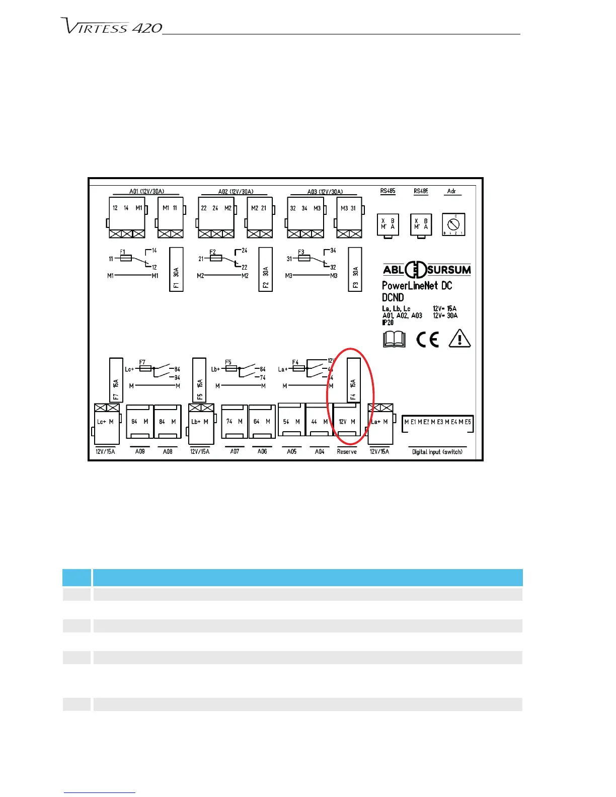
Oneachmodule(seenbelow)a15AmpslotservesasabackupandmaybeusedindependentlyoftheRS485-Bus.
One of the fuses may be moved manually to supply this circuit independently and permanently while overriding the
RS485BUS:ThebackupFuseishighlightedwiththeredellipseinthebelowdiagram.
7.5.2. Failureofthetouch-sensitiveDisplay
In this case all relays stay switched and connected as before the failure occurred. The relays will only be disabled if
thevoltageonthesystem(RS485BUS)isbeingswitchedoff.
7.5.3. The DC system consists of the following circuits/consumers:
Pos. Description
16 Analog box
17 Digital box
18 Mainswitchbowthruster,anchorwindlass(manual)(Option)
19 MainswitchConsumer(remotecontrol,receiver)(Batterydisconnectswitch)
20 Mainswitchengine1and2(remotecontrol,receiver)(Batterydisconnectswitch)
21 MainswitchGangway,aftplatform,sternwindlass(Sternanchor)windlass(remotecontrol,receiver)(Bat-
terydisconnectswitch)(Option)
22 Batteries(Consumer,engine;partlyoptional)
23 CockpitpanelHelmstand(Deck)
 Loading...