NOTE: Refer to oven installation checklist and
complete during initial start-up.
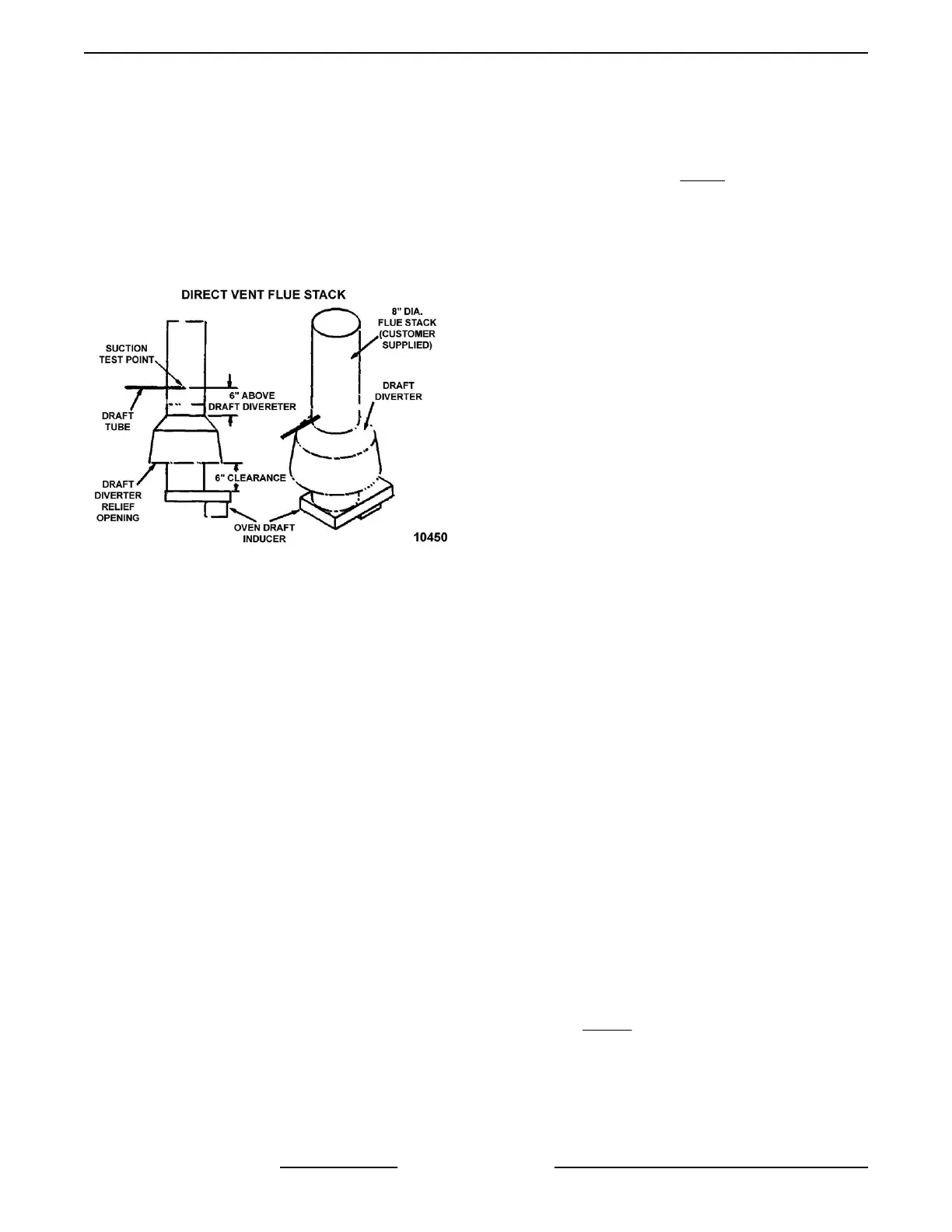
1. Verify flue draft (direct vent with gas oven only).
A. Insert a draft tube into the flue stack 6"
above the top of the draft diverter. If
required, drill a hole in flue stack to insert
draft tube.
B. Connect a incline manometer or equivalent
to the draft tube.
Fig. 6
C. With the oven turned off and doors closed,
check the manometer reading. Reading
should be a vacuum of 0.03" to 0.11" W.C.
1) If vacuum requirements are met,
proceed to step D.
2) If vacuum requirements are not met,
the customer supplied flue stack must
be modified to meet the above stated
requirements.
3) After flue stack change has been done,
repeat the procedure.
D. Operate the oven for a minimum of 5
minutes.
1) While burner is lit, check for a back
draft at the draft diverter relief opening
(i.e. smoke emitted from a smoldering
source).
2) If no back draft indicated (smoke going
up draft diverter relief opening) test is
complete.
3) If back draft indicated (smoke not going
up draft diverter relief opening) the
oven must not be operated, until proper
adjustments have been made (correct
flue stack to have adequate up draft
through the draft diverter relief
opening).
E. Verify oven rack rotates and baking
compartment circulation fan is turning. If not,
door switches will need to be adjusted, as
outlined under DOOR SWITCH
ADJUSTMENT Step 4.
NOTE: Baking compartment circulation fan will run
continuously with time entered in the bake timer and
cycle on/off with heating circuit if no time is entered in
the bake timer.
2. Ignition Sequence Check (Gas Ovens Only).
NOTE: Ignition module makes one attempt to light
burner before locking out.
NOTE: Remove power from ignition control module
by turning main circuit breaker to oven off or by
opening the loading doors for a minimum of 5
seconds.
A. Turn gas valve off to test ignition sequence
check.
B. Set oven to call for heat by pressing bake
temperature display UP ARROW key, until
HEAT ON LED illuminates.
C. Draft inducer energized for 15 seconds pre-
purge cycle.
D. Hot surface igniter glows indicating that it is
energized.
E. 2 seconds after igniter was energized, gas
valve solenoid is energized.
F. After igniter has been energized for 4
seconds, flame sensor will not have
recognized a flame.
1) Power is removed from igniter and gas
valve.
G. After initial try for ignition and the burner has
not lit, there will be an additional 15 second
purge time.
H. LED on ignition control will flash in a 3 flash
sequence indicating a flame recognition
failure and that the control is in lock-out
mode.
I. This indicates the safety lock-out circuit is
functioning properly.
NOTE: See IGNITION SEQUENCE TIMING
DIAGRAM Fig. 19
3. Gas Pressure Adjustment (Gas Ovens Only).
A. Remove the gas valve cover to access the
gas valve pressure taps.
OV310 Series Mini Rack Oven Installation Instructions - INSTALLING OVEN
F25422 Rev. B (0917) Page 10 of 16
 Loading...