Hardware
Setup
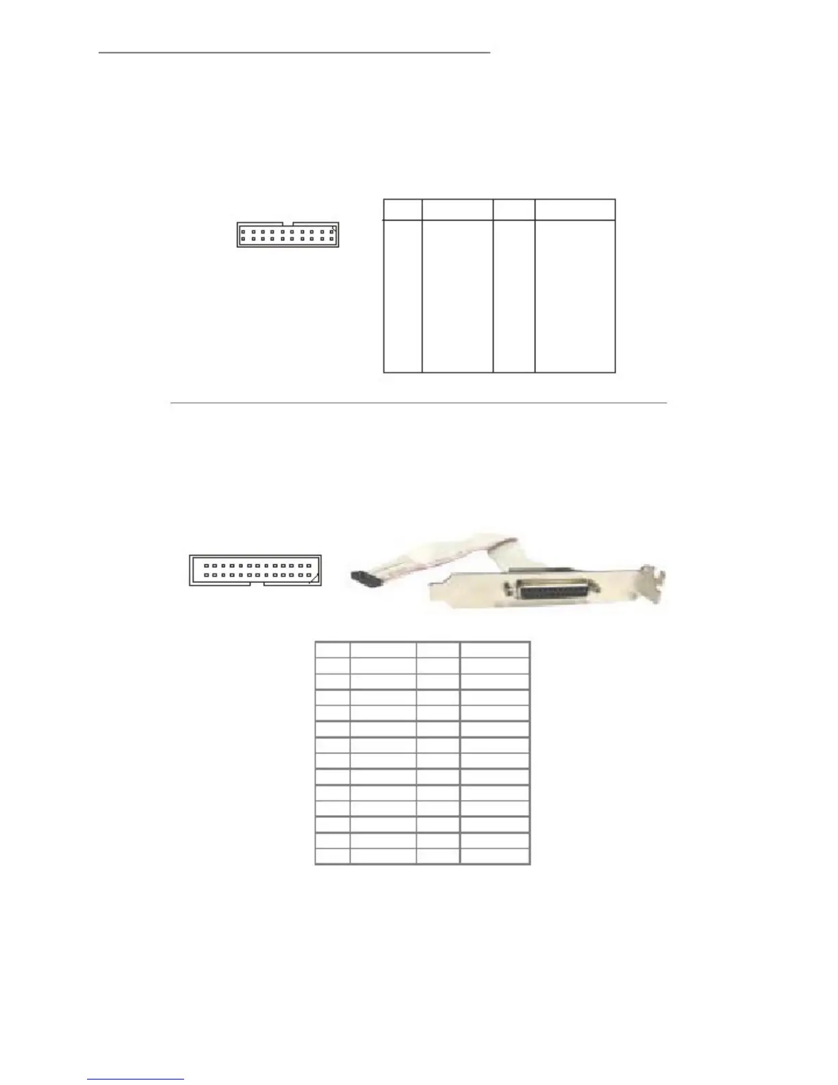
Digital IO Connector: J3
The J3 connects to the General-Purpose Input/Output
(GPIO) peripheral module.
J3 Pin Definition
J3
19
20
1
2
PIN
1
3
5
7
9
11
13
15
17
19
SIGNAL
VCC3
N_GPIO10
N_GPIO11
N_GPIO12
N_GPIO13
N_GPIO14
N_GPIO15
N_GPIO16
N_GPIO17
GND
PIN
2
4
6
8
10
12
14
16
18
20
SIGNAL
VCC5
N_GPIO20
N_GPIO21
N_GPIO22
N_GPIO23
N_GPIO24
N_GPIO25
N_GPIO26
N_GPIO27
NC
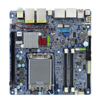
Parallel Port Header: JLPT1
The mainboard provides a 26-pin header for connec-
tion to a parallel port bracket. The parallel
port is a standard printer port that supports
Enhanced Parallel Port (EPP) and Extended Capabili-
ties Parallel Port (ECP) mode.
Parallel Port
JLPT1
2
1
26
25
Bracket
Pin
1
3
5
7
9
11
13
15
17
19
21
23
25
Signal Name
RSTB#
PRND0
PRND1
PRND2
PRND3
PRND4
PRND5
PRND6
PRND7