BDCOM GP3600-08 GPON Hardware Installation Manual
- 2 -
When PWR2 supplies power, this LED
is on.
When PWR1 supplies power, this LED
is on.
If the indicator is always on, the system
is being started.
If the indicator flickers, the system
works normally.
If the indicator is always off, the system
works normally;
If the indicator is on, the temperature of
the device is over high and need to
check.
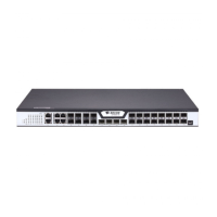
Gigabit ACT/link indicator
If the indicator is always on, the link on
the port is normal.
If the indicator flickers, the data is
received or transmitted through the
port.
If the indicator is always on, the link on
the port is normal.
If the indicator flickers, the data is
received or transmitted through the
port.
16 PON port ACT/link
indicators
If the indicator is on, the device has
been connected;
If the indicator flickers, the data is
received or transmitted through the
port.
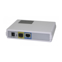
Manages GPON access device locally.
100M external management port.
Realizes the upgrade of the GPON
access device.
Forwards the 1000M Ethernet electric
signals.
Forwards the 1000M Ethernet optical
signals
Forwards the 10000M Ethernet optical