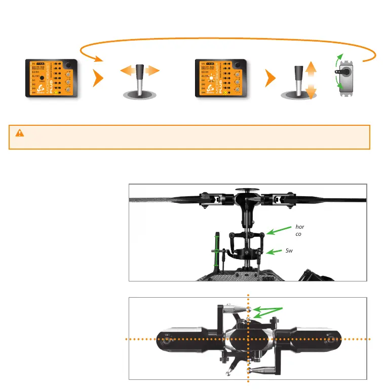
By moving the rudder stick into one direction repeatedly select one servo after another and adjust each servo‘s center position
by moving the elevator stick forwards or backwards so that the servo arm is positioned exactly 90 degrees to the linkage rod.
The servo number that is currently selected and that can be trimmed at the moment is indicated by the Status LED color.
When the servos are adjusted perfectly let one servo selected (only the electrical trim positions are important and are used in
the further steps) and adjust the linkage rods going from servos to the swashplate and from the swashplate to the blade grips.
Anti-rotation guide leveled
horizontally and twisted
correctly
Swashplate leveled horizontally
0° pitch
Swashplate centered
vertically on main shaft
Status LED o
(= no servo active)
Choose one of the servos
connected at CH1 - CH3
Move rudder stick
left or right
Status LED color indicates
selected servo number
Move elevator stick to adjust servo
center position
Check all servo positions by selecting each servo once even when the servo arms are perfectly positioned when
Status LED is off.
If necessary adjust the swashplate
anti-rotation guide so that there is no
swashplate phasing (only applies to
2-blade rotorheads).
Linkage balls of swashplate outer
ring and blade grips must be on
one line
The swashplate must be leveled
and centered on the main shaft
and the bladegrips should be set
to 0° pitch. Then briey push the
button to get to menu point H.