AR6201 - RT6201 - RCU6201 - AR6203
Page 2-2 DV 14307.03 Issue 1 09/2013
to Figure 2-1, Figure 2-2 and Figure 2-3. Leave a clearance of minimum 5 mm
between the AR6201 respectively RCU6201 and other avionics to allow air
circulation. Forced cooling is usually not required. For installation via
back-panel mounting four screws are already attached to the unit front. The
circular cut out and the mounting holes have to be prepared in accordance
with Figure 2-4.
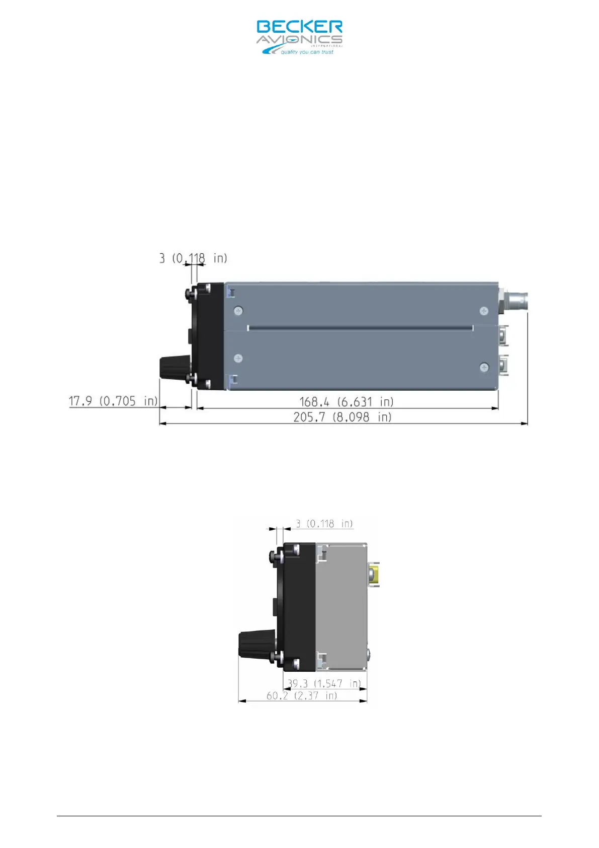
Figure 2-1: AR6201 side view, dimensions in mm and (inches)
Figure 2-2: RCU6201 side view, dimensions in mm and (inches)