Commissioning/application notes
CU1521-xxxx, CU1561 33Version: 2.5
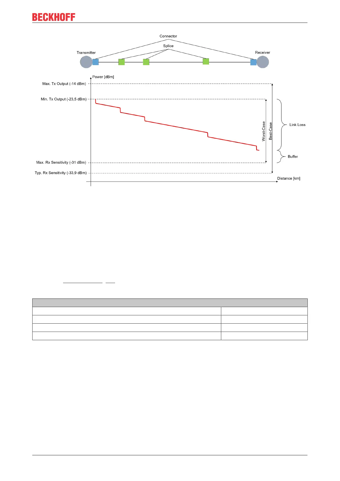
Fig.23: Power and attenuation budget
The attenuation level must not exceed the power level. A power buffer of >3dB is recommended so that
long-term operation is possible over many years despite power losses. Sources located in the transmitter
can age and lose power, connectors or splices can deteriorate, or connectors can become dirty if they are
opened for diverting or testing. If cables are inadvertently cut through, excess play is required in order to
accommodate splices for reconnecting.
Example calculation of power and attenuation budget
In an example calculation, the power and attenuation budget is to be calculated for a transmission link of
2.1km in length between an EK1501-0000 and an EK1521-0000 with a multimode fiber in the strength
50/125µm. The two fiber-optic couplers under consideration have the same transceiver. The optical data are
given in the Technical data [}18] for the EK1521.
First of all, the power budget existing between the two couplers must be calculated:
Power budget
Parameter Value
Minimum output power [50/125µm] -23.5dBm
Maximum sensitivity -31dBm
Power budget 7.5dBm
In the next step, the attenuation budget, i.e. the attenuation over the entire transmission link, must be
calculated. A multimode fiber in the strength 50/125µm from Beckhoff (ZK1091-1001-xxxx) is used for this
example. A maximum attenuation of 0.8dB/km at a wavelength of 1300nm is specified in the data sheet for
the fiber-optic cable. The cable is connected at both ends via an SC connector. The typical attenuation value
of SC connectors is 0.25 dB, but it should nevertheless be checked for the specific application. Three splices
were made over the entire link. A typical attenuation of 0.3dB can be assumed per splice connection;
however, the attenuation of a splice is dependent on its quality. The attenuation budget must be calculated
from these values in the following.