Product overview
EL34xx30 Version: 1.5
WARNING
WARNING Risk of electric shock!
The complete wiring of the EL34xx must be protected against accidental contact and equipped with associ-
ated warnings! The insulation should be designed for the maximum conductor voltage of the system to be
measured!
The EL34xx allows a maximum voltage of 480V for normal operating conditions. The conductor voltage on
the current side must not exceed this value! For higher voltages, an intermediate transformer stage should
be used!
An EL34xx is equipped with a protection impedance of typically 1.2MΩ on the voltage measurement side. If
the neutral conductor is not connected and only one connection on the side of the voltage measurement is
live, the resulting voltage against earth in a 3-phase system with a phase-to-phase voltage of 400V
AC
is
230V
AC
. This should also be measured on the side of the current measurement using a multimeter with an
internal resistance of 10MΩ, which does not represent an insulation fault.
Connection cable for current transformers
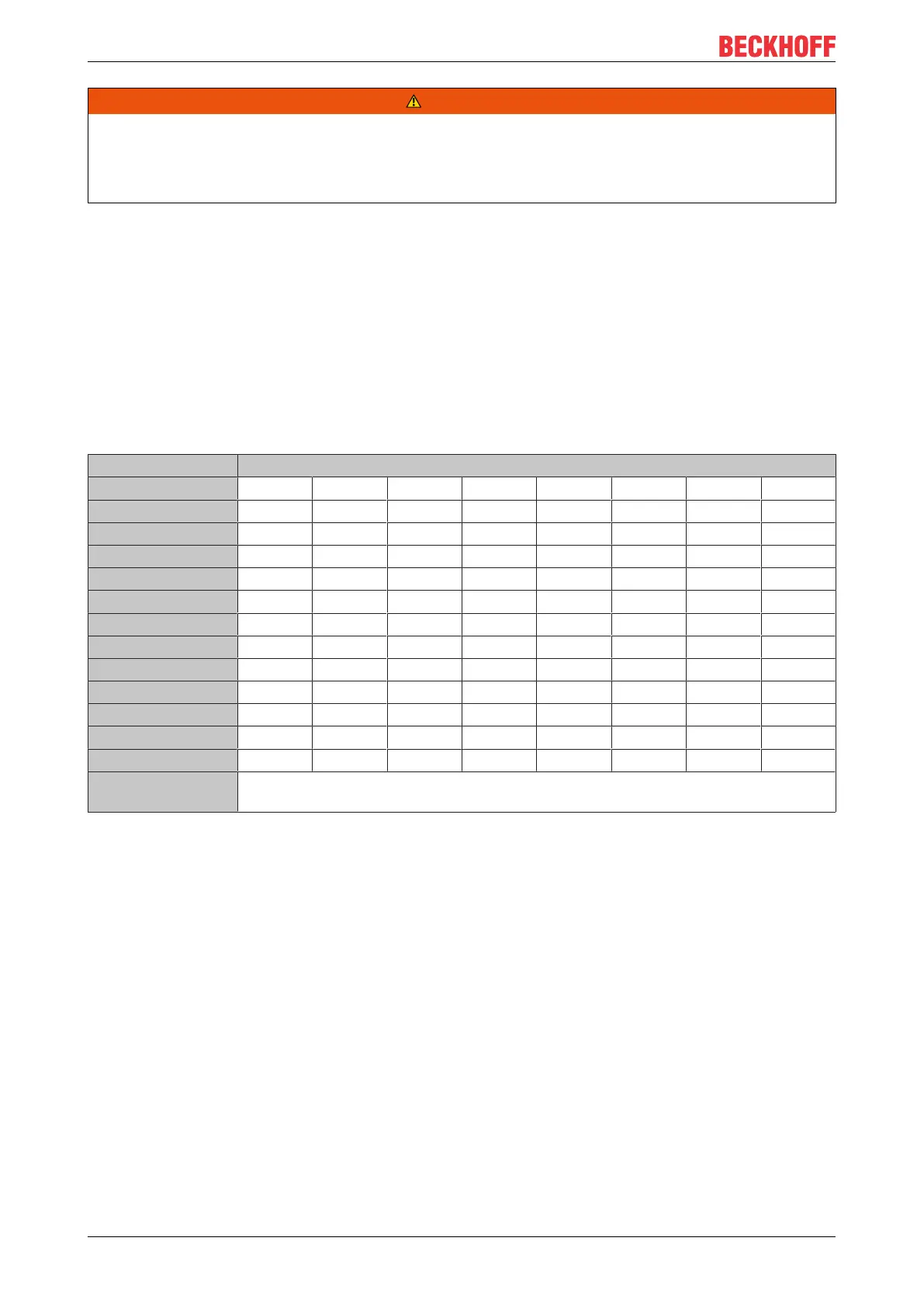
Please note the following minimum power values for current transformers to be connected:
Rated secondary transformer current
1 A 1 A 1 A 1 A 5 A 5 A 5 A 5 A
Cross-section 0.5 mm² 1 mm² 1.5 mm² 2.5 mm² 0.5 mm² 1 mm² 1.5 mm² 2.5 mm²
1 m 0.3 0.2 0.2 0.2 2.4 1.3 0.9 0.6
2 m 0.4 0.3 0.3 0.2 4.6 2.4 1.7 1.1
3 m 0.5 0.3 0.3 0.3 6.8 3.5 2.4 1.5
4 m 0.6 0.4 0.3 0.3 9.0 4.6 3.1 2.0
5 m 0.6 0.4 0.3 0.3 11.2 5.7 3.9 2.4
10 m 1.1 0.6 0.5 0.4 22.2 11.2 7.5 4.6
20 m 2.0 1.1 0.8 0.6 44.2 22.2 14.9 9.0
30 m 2.8 1.5 1.1 0.7 66.2 33.2 22.2 13.4
40 m 3.7 2.0 1.4 0.9 88.2 44.2 29.5 17.8
50 m 4.6 2.4 1.7 1.1 110.2 55.2 36.9 22.2
100 m 9.0 4.6 3.1 2.0 220.2 110.2 73.5 44.2
Cable length Minimum operating load in VA for current transformers with copper cables and 80°C
operating temperature
Additional measuring devices in the current circuit
Please note that the addition of additional measuring devices (e.g.ammeters) in the current circuit can lead
to a significant increase in the total apparent power.
Furthermore, connection I
N
of the EL34xx must represent a star point for the three secondary windings.
Additional measuring devices therefore have to be potential-free and must be wired accordingly.

 Loading...


