Product overview
EP1xxx 35Version: 2.5.0
2.9.4 Accelerometers
2 x 3G accelerometers
The EP1816-3008 EtherCAT Box features 2 3-axis accelerometers.
They are fitted on the underside the PCB at 90° angles.
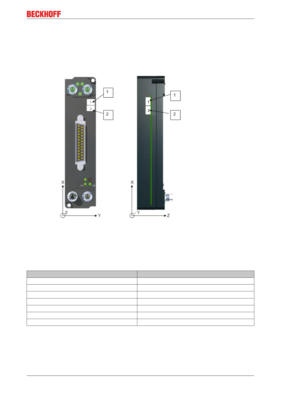
Fig.25: Location of the accelerometers
The image shows a top view and a side view of the EtherCAT Box. It shows the location of the
accelerometers within the Box. The green line indicates the location of the PCB. The accelerometers are
numbered 1 and 2. They are mounted on the underside of the PCB.
In this position, gravity (which is a form of acceleration), is displayed as a negative value when the Box is in
its normal operating position on a flat, level surface, e.g. on a test bench.
Process values Allocated acceleration value
AI Inputs Channel1 value Sensor 1, +X axis
AI Inputs Channel2 value Sensor 1, +Y axis
AI Inputs Channel3 value Sensor 1, -Z axis
AI Inputs Channel4 value Sensor 2, +Y axis
AI Inputs Channel5 value Sensor 2, -X axis
AI Inputs Channel6 value Sensor 2, -Z axis


 To Next Page