Overview of CoE objects EL6001, EL6021
EL600x, EL602x158 Version: 4.6
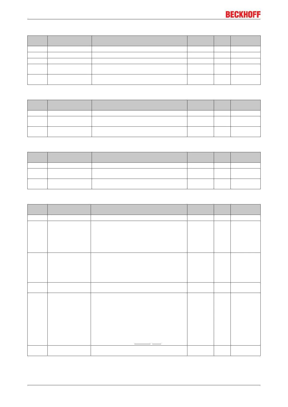
Index 0x1C00 Sync manager type
Index
(hex)
Name Meaning Data type Flags Default
1C00:0 Sync manager type Using the sync managers UINT8 RO 0x04 (4
dec
)
1C00:01 SubIndex 0x001 Sync-Manager Type Channel 1: Mailbox Write UINT8 RO 0x01 (1
dec
)
1C00:02 SubIndex 0x002 Sync-Manager Type Channel 2: Mailbox Read UINT8 RO 0x02 (2
dec
)
1C00:03 SubIndex 0x003 Sync-Manager Type Channel 3: Process Data Write
(Outputs)
UINT8 RO 0x03 (3
dec
)
1C00:04 SubIndex 0x004 Sync-Manager Type Channel 4: Process Data Read
(Inputs)
UINT8 RO 0x04 (4
dec
)
Index 0x1C12 RxPDO assign
Index
(hex)
Name Meaning Data type Flags Default
1C12:0 RxPDO assign PDO Assign Outputs UINT8 RW 0x01 (1
dec
)
1C12:01 SubIndex 0x001 1
st
allocated RxPDO (contains the index 0x of the as-
sociated RxPDO mapping object)
UINT16 RW 0x1602
(5634
dec
)
1C12:02 SubIndex 0x002 2
nd
allocated RxPDO (contains the index 0x of the as-
sociated RxPDO mapping object)
UINT16 RW 0x0000 (0
dec
)
Index 0x1C13 TxPDO assign
Index
(hex)
Name Meaning Data type Flags Default
1C13:0 TxPDO assign PDO Assign Inputs UINT8 RW 0x01 (1
dec
)
1C13:01 SubIndex 0x001 1
st
allocated TxPDO (contains the index 0x of the as-
sociated TxPDO mapping object)
UINT16 RW 0x1A02
(6658
dec
)
1C13:02 SubIndex 0x002 2
nd
allocated TxPDO (contains the index 0x of the as-
sociated TxPDO mapping object)
UINT16 RW 0x0000 (0
dec
)
Index 0x1C32 SM output parameter [from hardware version 03]
Index
(hex)
Name Meaning Data type Flags Default
1C32:0 SM output parameter Synchronization parameters for the outputs UINT8 RO 0x20 (32
dec
)
1C32:01 Sync mode Current synchronization mode:
• 0: Free Run
• 1: Synchron with SM 2 Event
• 2: DC-Mode - Synchron with SYNC0 Event
• 3: DC-Mode - Synchron with SYNC1 Event
UINT16 RW 0x0001 (1
dec
)
1C32:02 Cycle time Cycle time (in ns):
• Free Run: Cycle time of the local timer
• Synchronous with SM 2 event: Master cycle
time
• DC-Mode: SYNC0/SYNC1 Cycle Time
UINT32 RW 0x0007A120
(500000
dec
)
1C32:03 Shift time Time between SYNC0 event and output of the outputs
(in ns, DC mode only)
UINT32 RO 0x00000000
(0
dec
)
1C32:04 Sync modes supported Supported synchronization modes:
• Bit 0 = 1: free run is supported
• Bit 1 = 1: Synchronous with SM 2 event is
supported
• Bit 2-3 = 01: DC mode is supported
• Bit 4-5 = 10: Output shift with SYNC1 event
(only DC mode)
• Bit 14 = 1: dynamic times (measurement
through writing of 1C32:08 [}158])
UINT16 RO 0xC007
(49159
dec
)
1C32:05 Minimum cycle time Minimum cycle time (in ns) UINT32 RO 0x00004E20
(20000
dec
)
 Loading...