Mounting and wiring
KL279118 Version: 2.0.0
3.2.3 Pin assignment
WARNING
Risk of injury through electric shock and damage to the device!
Bring the Bus Terminals system into a safe, de-energized state before starting mounting,
disassembly or wiring of the Bus Terminals!
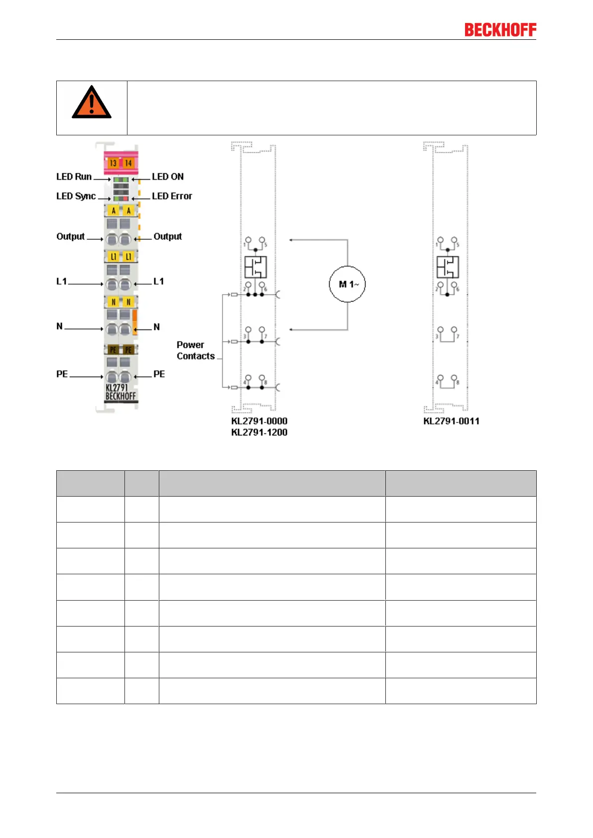
Fig.11: Pin assignment
Terminal
point
No. KL2791-0000,
KL2791-1200, connection for
KL2791-0011, connection for
Output 1 Load (internally connected with terminal point 5) Load (internally connected with
terminal point 5)
L1 2 Phase (internally connected with terminal point 6
and power contact for L1)
Phase (internally connected with
terminal point 6)
N 3 Neutral conductor (internally connected with
terminal point 7 and power contact for N)
Neutral conductor (internally
connected with terminal point 7)
PE 4 Protective conductor (internally connected with
terminal point 8 and power contact for PE)
Protective conductor (internally
connected with terminal point 8)
Output 5 Load (internally connected with terminal point 1) Load (internally connected with
terminal point 1)
L1 6 Phase (internally connected with terminal point 2
and power contact for L1)
Phase (internally connected with
terminal point 2)
N 7 Neutral conductor (internally connected with
terminal point 3 and power contact for N)
Neutral conductor (internally
connected with terminal point 3)
PE 8 Protective conductor (internally connected with
terminal point 4 and power contact for PE)
Protective conductor (internally
connected with terminal point 4)
Power feed terminal
A power feed terminal can supply several speed controller terminals.
 Loading...


