14
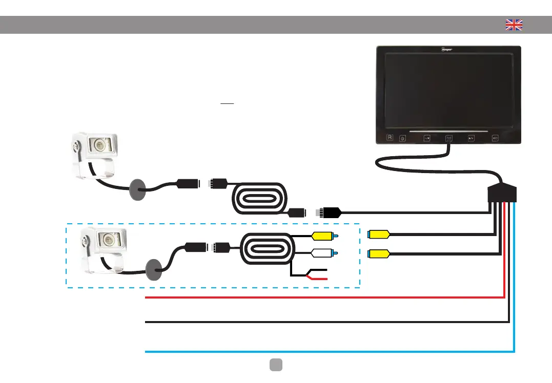
2. SYSTEM CONNECTION
POSITION OF THE CAMERA
• Connect the extension of 20 meters between the screen and the camera
• Connect the beam (6 son) on the screen
• Connect the BLACK wire to the original mass
• Connect the RED wire to ignition +12 V source (15)
• Connect the BLUE wire to the +12 V reverse light
Note: You can connect this wire to +12 V
after ignition if you want to use this product
as electronic mirror (see next page)
Camera
7ʼʼ LED Display
4 pins screw
connection
20 meters
extension
4 pin screw
connection
Input CAMERA
Connecting the camera included in the pack
Input VIDEO IN 1
Optional camera (not supplied)
+ 12V after ignition
• RED
Automatic activation display
Ground
• BLACK
Alimentation (-)
+ 12V Reversing light
• BLEU
Switching the camera at the passage
of the reverse
Input VIDEO IN 2
Optional camera (not supplied)
Optional camera connection
(not supplied)
20 meters
extension
Ref : RX-45/20
DO NOT
CONNECT
BLACK• Ground
RED •+ 12V
After ignition