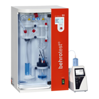
Front view of the behr S 5
Figure 3: Diagram legend
4.1 Operating control unit: Chemical-resistant
plastic foil
4.17 Distillate level sensors (the 2nd is hidden
behind the stirrer)
4.2 Liquid crystal display (LCD) 4.18 Protection vessel for pH electrode
4.3 Control knob 4.19 Drip tray
4.4 Cooling water outlet 4.20 PTFE steam delivery tube
4.5 Screw-on connectors GL 14 4.21 Notch for positioning the steam delivery tube
between distillations
4.6 Cooling water inlet 4.22 Quick release fastener for holding the sample
vessels during distillation
4.7 Distillate suction tube, silicone 4.23 Plexiglass protective door (not shown)
4.8 Silicone delivery tube for H
3
BO
3
4.24 Fastening screws for glassware mounting
4.9 Opening for electrode cable and titration tube 4.25 Glassware mounting
4.10 Distillate delivery tube, silicone 8/12 4.26 Viton stopper for sealing vessel mouth
4.11 Air release valve 4.27 GL 18 screw-on connectors with silicone gaskets
4.12 Titration device 4.28 PTFE delivery tube for NaOH
4.13 Stirrer 4.29 Distillation head, glass
4.14 Titration vessel 4.30 Polypropylene steam/water inlet junction with
polypropylene nut
4.15 Electrical power switch 4.31 GL 32 screw-on connector with silicone gasket
4.16 Lid opening for pH electrode 4.32 Condenser
Front view