18 19Quick Start GuideSYNCUSSION SY-1
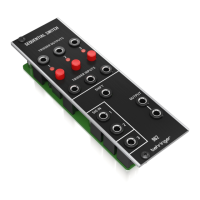
SYNCUSSION SY-1 Controls
(EN)
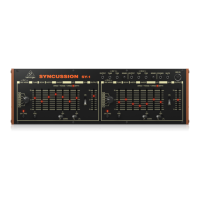
Step 2: Controls
TOP PANEL
(1)(2)(3)(4)(5)(6)(7)(8)(9)(10) (11)
12)
(14)(15)(16)(17)(19)(20) (23) (24) (25)
(26) (27) (28)(29)(30)(31)(32) (35)(34) (39)(38)
(36
(37
(33)
Sockets 1 – 3 and 5 – 7 and controls 4 and 8 are duplicates relating to channels 1 and 2
(1) & (5) – OUTPUTS – use these unbalanced 3.5 mm TR jack sockets to get the individual outputs of channels 1 and 2.
(2) & (6) – TUNE – use these sockets to adjust the channel tuning using an external device such as a footpedal. This is a TS socket, and
does not output a voltage for the external source to manipulate.
(3) & (7) – TRIGGER – use these sockets to trigger the channels from an external trigger source.
(4) & (8) – SENSE – use these controls to adjust the sensitivity of the trigger inputs, to prevent mis-triggering.
(9) PHONES – use this stereo TRS 3.5 mm jack socket to monitor the output of the SY-1 with a suitable set of headphones.
(10) MUTE – use this socket to cut o the decay of the SY-1 with an external footswitch.
(11) MIDI IN – use this 5 pin DIN socket to control the SY-1 using MIDI.
The controls, switches and LEDs 12 – 25 and 26 – 39 are duplicates relating to channels 1 and 2.
(12) & (26) – OSC MODE – use these switches to set the oscillator mode for each channel. There are six modes available
A – Single oscillator
B – Two oscillator FM
C – Two oscillator mix
D – Two oscillator mix, with sweep dependent on trigger strength rather than sweep settings
E – Two oscillator FM with added white noise
F – White noise only
(13) & (27) – TRIGGER – use these buttons to trigger the SY-1 without using an external trigger source. The LED lights up when a channel
is triggered, internally or externally.
(14) & (28) – TUNE – use these controls to tune the SY-1 oscillators to a specic frequency. The fader provides coarse tuning, the ne pot
allows accurate adjustment.
(15) & (29) – DECAY – use these controls to set the decay time of the channels, from 6 ms to 2.5 s dependent on tuning setting.
(16) & (30) – WIDTH – use these controls to set the lter cuto frequency.
(17) & (31) – SWEEP SPEED – use these controls to set the speed that the oscillators’ pitch will be swept, depending on the settings of
switches 18 and 32.
(18) & (32) – SWEEP SWITCHES – use these switches to set the oscillators’ pitch sweep to up, down or o.
(19) & (33) – SWEEP RANGE – use these controls to set the range of the pitch sweep.
(20) & (34) – LFO SPEED – use these controls to set the speed of the LFOs, from 0.4 Hz to 50 Hz.
(21) & (35) – LFO WAVE – use these switches to select the LFO waveform (square or triangle); or to turn the LFO o.
(22) & (36) – LFO LED – these LEDs ash at the speed of the LFOs.
(23) & (37) – LFO DEPTH – use these controls to set the depth of LFO modulation.
(24) & (38) – S&H – use these switches to turn sample and hold modulation on or o. The sample rate is set by the LFO speed (controls 20
& 34) and will operate even if the LFO switches (21 & 35) are set to OFF.
(25) & (39) – OUTPUT – use these controls to set the output levels of the two channels.
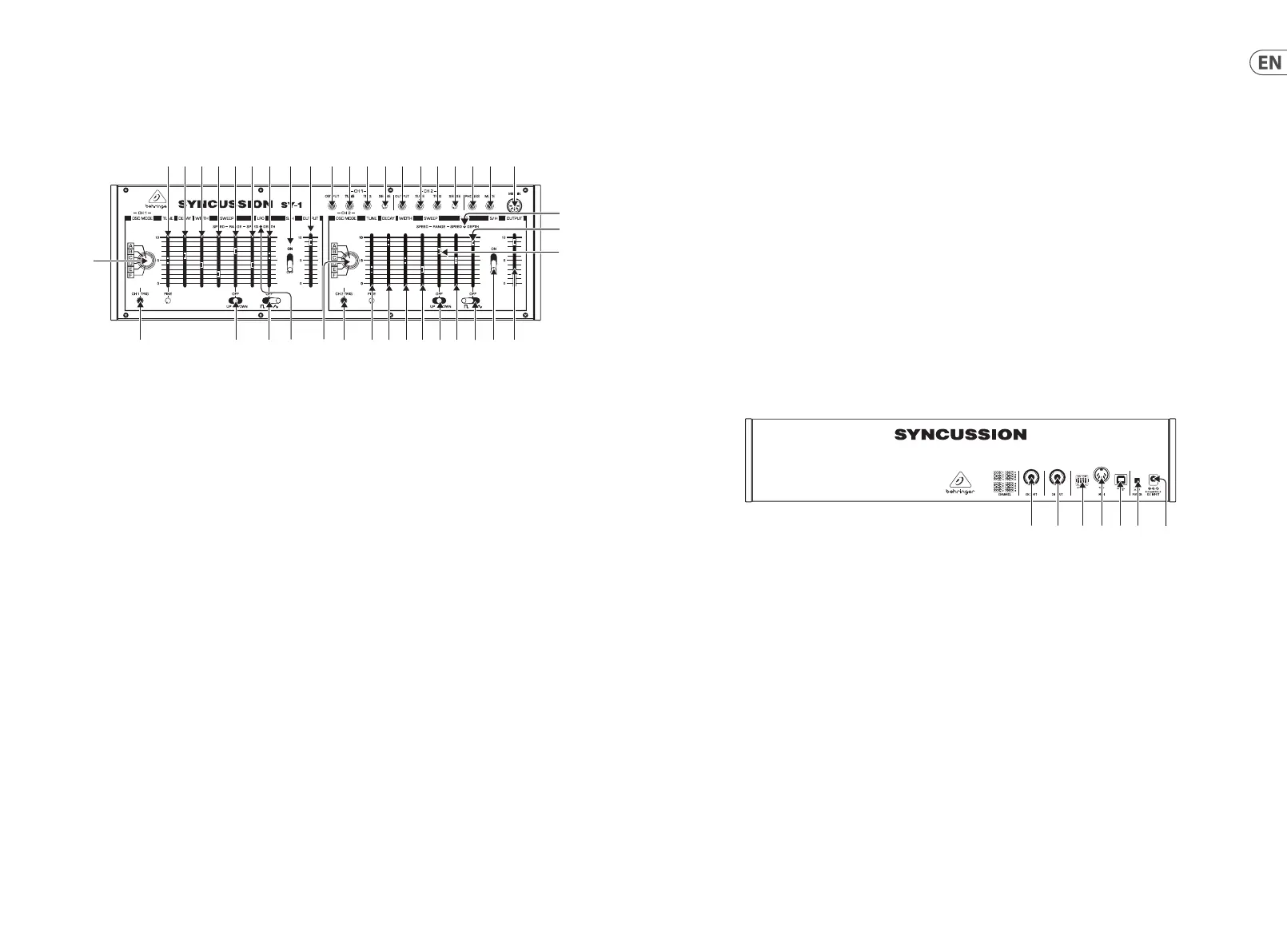
REAR PANEL
(40)(41) (42) (43) (44)(45) (46)
(40) CHANNEL 1 OUTPUT – use this 6.35mm unbalanced TR jack socket to feed the output of Channel 1 to an external amplier or mixer.
This output is duplicated by socket 1 on the top panel.
(41) CHANNEL 2 OUTPUT – use this 6.35mm unbalanced TR jack socket to feed the output of Channel 2 to an external amplier or mixer.
This output is duplicated by socket 5 on the top panel.