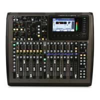
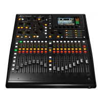
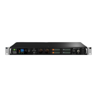
16 17X32 CORE DIGITAL RACK MIXER Quick Start Guide
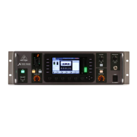
X32 CORE DIGITAL RACK MIXER Select Knob Functions
(EN) Step 3: Select Knob
Functions
The SELECT knob serves several functions on the X32 CORE. The following table describes the SELECT knob
behavior in each of the available scenarios.
Action
Functional Description
Channel Select Mode (SCENE/SETUP button LED is o)
Display >Selected channel number
>Input source
>Channel icon and color
>Nickname
Short press Toggles the selected channel to SOLO on/o
> Channel signal will be sent to Monitoring L/R outputs on rear panel and Phones
output on front panel
> Exact behavior depends on settings in Monitoring page (remote controlled via
editing software)
Rotate Immediately selects the desired channel
(input, aux in, FX return, bus, matrix, main or DCA)
>The Channel Type LEDs [5] will follow the selection.
> Note that the X32 CORE Channel Selector will skip all channels, setting the
display color to ’black’ or ’o’.
Long press Clears all active channel solos
Scene Select Mode (accessed by pressing the SCENE/SETUP button so that the LED is green)
Display >“Scene” in bold
>Current scene number
>Next scene number and name (small) to be loaded on GO
Short press Recalls the selected Scene from X32 internal memory “GO”
> behavior depends on Scene settings/preferences (remote controlled via
editing software)
> Scene safes can only be set/reset remotely
> Scenes/Shows from USB drives can only be accessed remotely
>A complete show can be loaded from an attached USB drive into the internal
memory using Setup Mode
Rotate Preselects the next Scene
Setup Mode (accessed by pressing and holding the SCENE/SETUP button so that the LED is green)
Rotate and press Select and enter the Setup pages:
1. Load Show
2. Contrast
3. LEDs
4. Clock Rate
5. Sync
6. IP Address
7. IP (Subnet) Mask
8. IP Gateway
9. Lock
1. Load Show Load show from root directory of attached USB drive
>display 3 rows:
-Load Show
-Exit
-Show Files
>Exit leads back to Setup Mode root level
>Turn clockwise to scroll through a list of show les found in USB root directory,
push to load selected show and return to Setup Mode root level
2. Contrast LCD contrast
> Rotate to adjust 0-100
> Press to conrm and exit
Action
Functional Description
3. LEDs LED brightness
> Rotate to adjust 0-100
> Press to conrm and exit
4. Clock Rate Select the internal Sample Clock Rate
> Rotate to adjust 44.1 or 48 kHz (change requires to reboot the X32 CORE)
> Press to conrm and exit
5. Sync Choose Clock Synchronization source
> Rotate to select INT (internal), AES50 (Port) A, or AES50 (Port) B
> Press to conrm and exit
6. IP Address Select the IP Address for X32 CORE
> Rotate to adjust the rst triplet (0-255)
> Press to conrm
> Rotate to adjust the second triplet (0-255)
> Press to conrm
> Rotate to adjust the third triplet (0-255)
> Press to conrm
> Rotate to adjust the fourth triplet (0-255)
> Press to conrm and exit
7. IP Mask Select the IP Subnet Mask for X32 CORE
> Rotate to adjust the rst triplet (0-255)
> Press to conrm
> Rotate to adjust the second triplet (0-255)
> Press to conrm
> Rotate to adjust the third triplet (0-255)
> Press to conrm
> Rotate to adjust the fourth triplet (0-255)
> Press to conrm and exit
8. IP Gateway Select the IP Gateway for X32 CORE
> Rotate to adjust the rst triplet (0-255)
> Press to conrm
> Rotate to adjust the second triplet (0-255)
> Press to conrm
> Rotate to adjust the third triplet (0-255)
> Press to conrm
> Rotate to adjust the fourth triplet (0-255)
> Press to conrm and exit
9. Lock Locks the X32 CORE
>Display “Lock Cancel”
>Press to cancel locking
> Rotating clockwise turns the display from Green to Red backlight and
shows “LOCKED”
> Press and hold the SCENE/SETUP button for 5 seconds in order to exit Locked
mode and get back to the standard Channel Select mode (showing the last
selected channel)