8
XENYX
502/802/1002/1202
CD/TAPE OUTPUT
These connectors are wired in parallel with the MAIN OUT and
carry the main mix signal (unbalanced). Connect the CD/TAPE
OUTPUT to the inputs of your recording device. The output level
is adjusted via the high-precision MAIN MIX fader or rotary
control (802).
2.3.4 Signal assignment
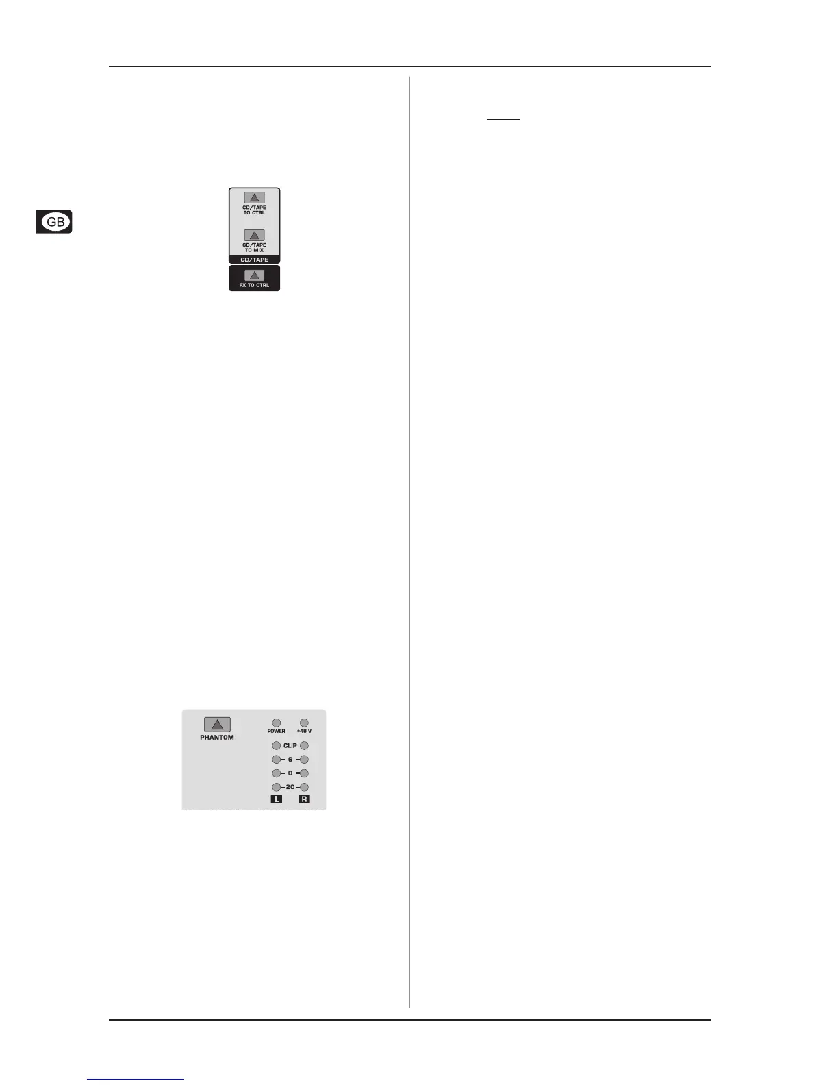
Fig. 2.12: Assignment switches of the main section
CD/TAPE TO MIX
When the TAPE TO MIX switch is depressed, the 2-track
input is assigned to the main mix providing an additional input for
tape machines, MIDI instruments or other signal sources that do
not require any processing.
CD/TAPE TO CTRL ROOM (502: CD/TAPE TO PHONES)
Press the CD/TAPE TO CTRL ROOM/PHONES switch if you
want to monitor the 2-track input via the CTRL ROOM OUT. This
provides an easy way to monitor signals coming back from tape
to ensure that they are recording correctly.
+ If you are recording a signal via the CD/TAPE OUTPUT
and wish to listen to this simultaneously via the
CD/TAPE INPUT, do not use the CD/TAPE TO MIX
switch. Doing this would create a feedback loop,
since the signal would be routed, via the main mix,
back to tape via the CD/TAPE OUTPUT. To monitor
the CD/TAPE INPUT, use the CD/TAPE TO CTRL ROOM
switch to assign the tape signal to the monitor(s)
or headphones. This will avoid the tape signal being
routed to the CD/TAPE OUTPUT.
FX TO CTRL ROOM
If you want to monitor only the FX send signal in your
headphones or monitor speaker(s), press the FX TO CTRL
switch. This mutes the main mix signal while routing the FX SEND
output to the monitor(s). The XENYX 802 and 502 do not feature
this switch.
2.3.5 Phantom power and LED displays
Fig. 2.13: Phantom power and control LEDs
+48 V (802/1002/1202 only)
The red +48 V LED lights up when phantom power is on. The
PHANTOM switch activates the phantom power supply on the
XLR connectors of all mono channels.
+ Please do not connect microphones to the mixer
(or the stagebox/wallbox) as long as the phantom
power supply is switched on. Connect the micro-
phones before you switch on the power supply. In
addition, the monitor/PA loudspeakers should be
muted before you activate the phantom power
supply. After switching on, wait approx. one minute
in order to allow system stabilization.
POWER
The blue POWER LED indicates that the console is powered on.
LEVEL INDICATOR
The high-precision 4-segment display accurately displays the
relevant signal level.
LEVEL SETTING:
To correctly set the gains of the channels, first set the LEVEL
controls of the input channels to their center positions (0 dB).
Then use the TRIM controls to increase the input amplification
until signal peaks show 0 dB on the level meter.
When recording to digital recorders, the recorders peak meter
should not go into overload. While analog recorders can be
overloaded to some extent, creating only a certain amount of distortion
(which is common and often desirable), digital recorders distort
quickly when overloaded. In addition, digital distortion is not only
undesirable, but also renders your recording completely useless.
+ The peak meters of your XENYX display the level
virtually independent of frequency. A recording level
of 0 dB is recommended for all signal types.
2. CONTROL ELEMENTS AND CONNECTORS
 Loading...