10 XENYX X1204USB/1204USB User Manual
3. Digital Eects Processor
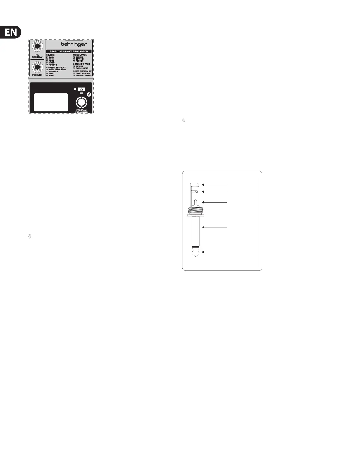
Fig. 3.1: Digital eects module (only X1204USB)
24-BIT MULTI-EFFECTS PROCESSOR
Here you can nd a list of all presets stored in the multi-eects processor.
This built-in eects module produces high-grade standard eects such as
reverb, chorus, anger, delay and various combination eects. The integrated
eects module has the advantage of requiring no wiring. This way, the danger
of creating ground loops or uneven signal levels is eliminated at the outset,
completely simplifying the handling.
These eect presets are designed to be added to dry signals. If you move the
FXTO MAIN control, you mix the channel signal (dry) and the eect signal.
This also goes for mixing eects signals with the monitor mix. The main
dierence is that the mix ratio is adjusted using the FX TO MON control. Of course,
a signal has to be fed into the eects processor via the FX control in the channel
strip for both applications.
◊ On the following page, you will find an illustration showing how to
connect your foot switch correctly.
LEVEL
The LED level meter on the eects module should display a suciently high
level. Take care to ensure that the clip LED only lights up at peak levels. If it is
lit constantly, you are overloading the eects processor and this could cause
unpleasant distortion. The FX control (AUX SEND 2) determines the level that
reaches the eects module.
PROGRAM
You can select the eect preset by turning the PROGRAM control. The display
ashes the number of the current preset. To recall the selected preset, pressthe
button; the ashing stops. You can also recall the selected preset with the
footswitch.
4. Installation
4.1 Rack mounting
The packaging of your mixing console contains two 19" rack mount wings which
can be installed on the side panels of the console.
Before you can attach the rack mount wings to the mixing console, you need to
remove the screws holding the left and right side panels. Use these screws to
fasten the two wings onto the console, being careful to note that each wing ts
a specic side. With the rack mount wings installed, you can mount the mixing
console in a commercially available 19" rack. Be sure to allow for proper air ow
around the unit, and do not place the mixing console close to radiators or power
amps, so as to avoid overheating.
◊ Only use the screws holding the mixing console side panels to fasten
the 19" rack mounts.
4.2 Cable connections
You will need a large number of cables for the various connections to and from
the console. The illustrations below show the wiring of these cables. Be sure to
use only high-grade cables.
strain relief clamp
sleeve
tip
sleeve
pole 1/ground
tip
pole 2
The footswitch connects both poles momentarily
¼" TS footswitch connector
Fig. 4.1: ¼" TS connector for foot switch
 Loading...