BELARUS-920.4/952.4 Operating manual
11
Scale of fuel gauge 1 (Fig. 1.3) has sections 0 – 1/4 – 1/2 – 3/4 – 1.
Alarm lamp 1.1 is built into the gauge scale (Fig. 1.3) (orange), which lights up when fuel quantity
in tank drops down to 1/8 of total tank capacity.
ATTENTION: AVOID USING THE FUEL TO REACH THE STATE OF “DRY TANK” (IN-
DICATOR NEEDLE IS IN ORANGE AREA)
Scale of pneumatic system air pressure gauge 2 (Fig. 1.3) has three areas:
- operating area – from 500 to 800 kPa (green);
- emergency area (two) – from 0 to 500 kPa and from 800 to 1000 kPa (red).
Alarm lamp 2.1 (Fig. 1.3) (red) is built into the gauge scale, and it lights up when pneumatic pres-
sure drops down below 500 kPa.
Voltage indicator 3 (Fig. 1.3) shows storage batteries voltage with shut-down engine, when the switch
key of starter and instruments (Fig. 1.2) is in I position. When the engine is running, voltage indicator
shows voltage across generator terminals. Red alarm lamp 3.1 (Fig. 1.3) is built into the voltage in-
dicator scale. It is used only in 24V starting system, shows the charging process of the second stor-
age battery with 24V voltage, tests performance of voltage converter.
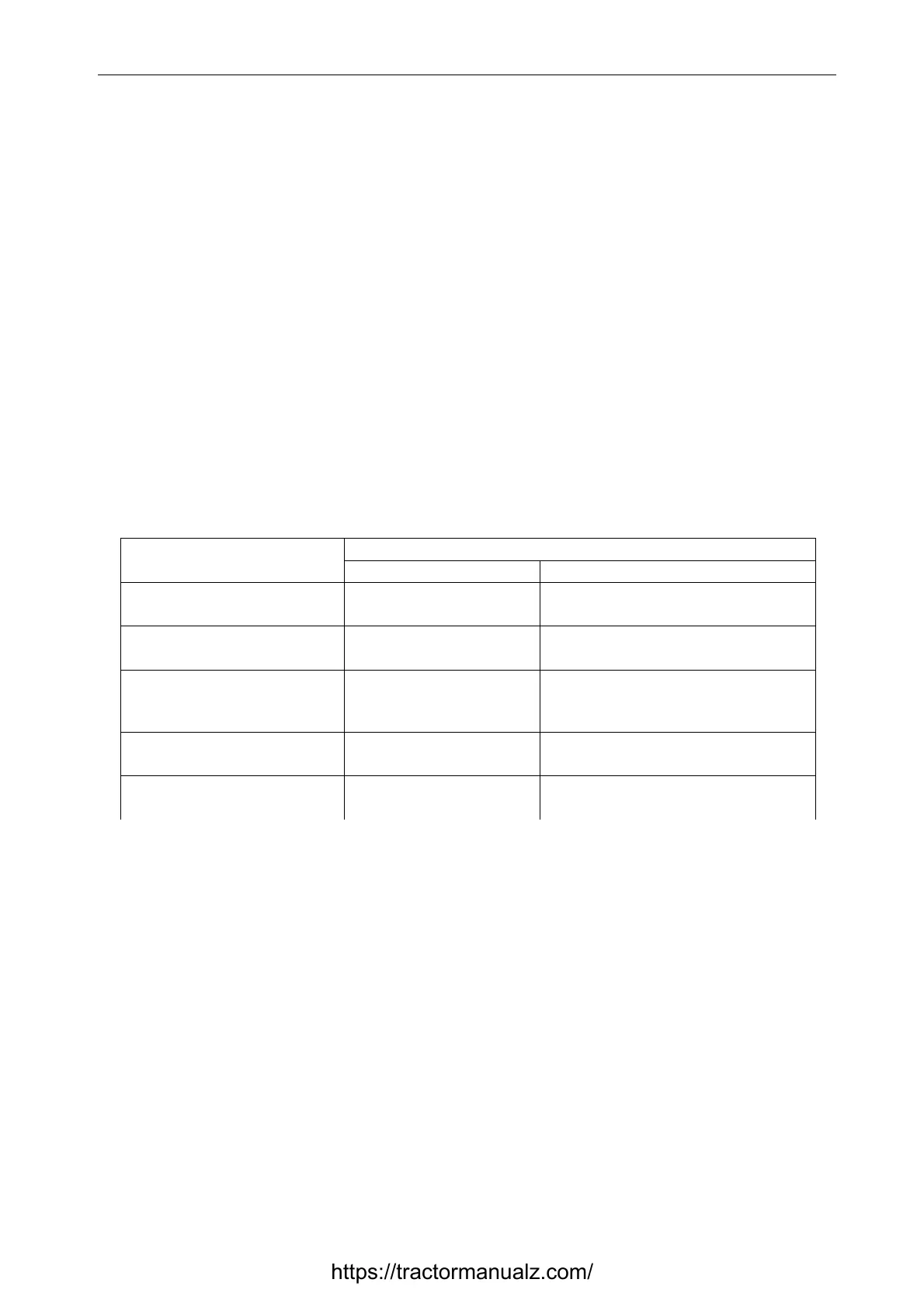
State of power-supply system
Table 2
Area on the scale of voltage
indicator 3 (Fig. 1.3), color
State of power-supply system
with running engine with shut-down engine
13.0 – 15.0 V
green
normal charging func-
tion
-
10.0 – 12.0 V
red
generator is out of oper-
ation
Storage battery is discharged
12.0 – 13.0 V
yellow
no storage battery charg-
ing (low charging voltage)
Storage battery has normal charge
15.0 – 16.0 V
red
Overcharging of storage
battery
-
white matchmark in yellow
area
- Rated EMF of Storage battery – 12.7 V
ATTENTION: IF VOLTAGE INDICATOR DISPLAYS ABSENCE OF STORAGE BATTERY
CHARGING, CHECK THE STATE AND TENSION OF GENERATOR DRIVING BELT
Engine coolant temperature gauge 4 (Fig. 1.3) reads information from engine control module
(ECM). Gauge scale has three areas:
- operating area — from 70 to 100 °С (green).
- information area — from 40 to 70 °С (yellow)
- emergency area — from 105 to 120 °С (red).
High temperature alarm lamp (red) 4.1 (Fig. 1.3) is built into the gauge scale, it works in two
modes:
a) – lights up and works in a flashing mode at coolant temperature values from 109 to 112 °С in-
clusive.
b) – is constantly glows at coolant temperature values from 113 °С and above.
Engine lubricating system oil pressure indicator 5 (Fig. 1.3) reads information from engine control
module (ECM). Gauge scale has three areas:
- operating area — from 100 to 500 kPa (green);
- emergency areas (two) — 0 to 100 kPa and from 500 to 600 kPa (red).
https://tractormanualz.com/