BELARUS-920.4/952.4 Operating manual
29
Annex to
Figure 2.4: Elements of wiring diagram for outer part of engine control system for
D-245.43S3А (D-245.5S3А) of tractors “BELARUS-920.4/952.4”:
1 - switching and security unit,
2 - CAN bus connector,
3 - forward trace accelerator pedal,
4 – diagnostics indicator,
5 – diagnostics button,
6 – information display,
7 – plug connector for diagnostic device connection,
8 – plug connector (89 pins),
9 – hand fuel supply sensor.
Annex B contains the electric circuit diagram of rear axle DL and PTO drive control system of
BELARUS – 920.4/952.4 tractors with list of components.
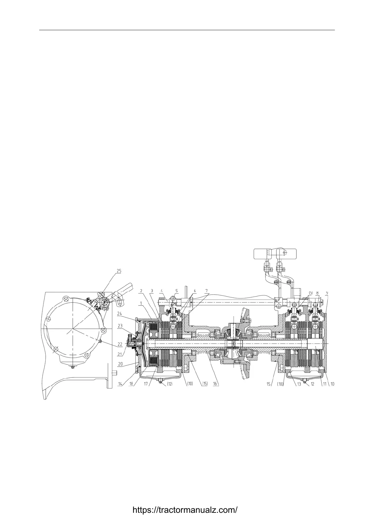
2.3 Wet brakes and rear axle differential lock clutch
2.3.1 General information
In order to improve tractor brakes energy consumption, their reliability and durability, brakes
operating in oil bath (wet brakes) are designed and installed on tractors “BELARUS-920.4/952.4”.
The rear axle differential lock clutch is mounted in the brake housing, both within the same oil
bath, thus the clutch is also designed as wet. Figure 2.5 presents the design of wet brakes and rear
axle differential lock clutch
1 — body housing, 2 — friction disk, 3 — spacing disk; 4 — pedal shaft; 5 — sealing hood;
6 — pressure plate; 7 - ball. 8 — park brake, 9 — cover; 10 — gasket; 11 — park brake shaft, 12 —
drain plug, 13 — brake housing; 14 — gasket; 15 — O-ring; 16 — axle drive gear; 17 — lock
clutch; 18 — hub, 20 — cover; 21 — adapter; 22 — check (filler) plug; 23 — sealing hood; 24 —
O-ring; 25 — adjusting bolt.
Figure 2.5 – Design of wet brakes and rear axle differential lock clutch
https://tractormanualz.com/