BELARUS-920.4/952.4 Operating manual
38
4. To discharge the coolant from the engine heater and cooling system, install the tractor on
an even surface. Remove the extension tank plug of the engine cooling system, open the valve on
the cylinder block in the rear part of the engine and disconnect the heater hoses before the entry to
the cab posts.
ATTENTION: WHEN WORKING IN THE HEATING MODE, THE SWITCH 2 (FIG-
URE 2.10) MUST BE FULLY OFF TO PREVENT SIMULTANEOUS OPERATION OF THE
AIR HEATING AND COOLING SYSTEMS.
2.5.3 General arrangement and operation of cab air conditioning and heating
system
The cab air conditioning and heating system is intended to create and maintain normal mi-
croclimate in the tractor cab. The air conditioning system consists of two circuits — cooling and
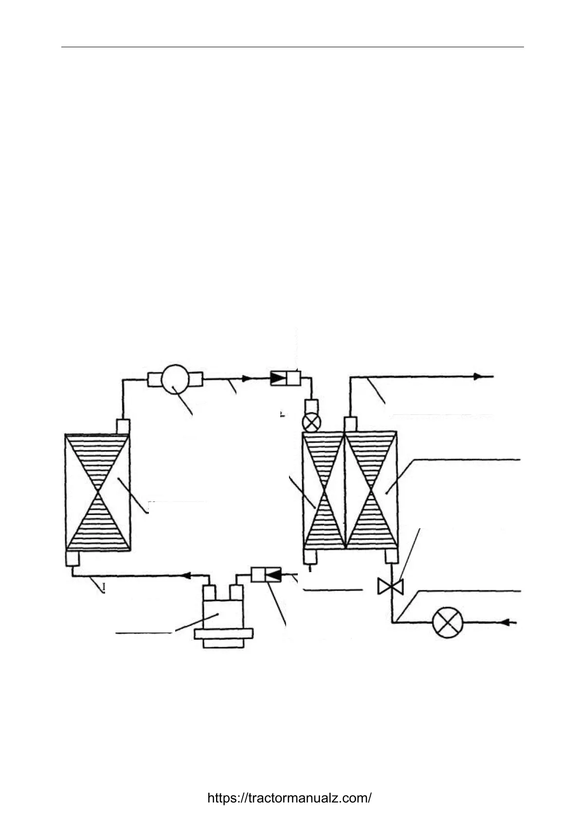
heating. Figure 2.11 shows the system layout.
The cooling circuit includes a compressor, a condenser, a filter drain with pressure sensor,
an evaporator and heat exchanger unit (cooler-heater), a cooler-heater fan, connection hoses with a
set of quick couplings, electric cables, air filters, a cool air regulator and a fan switch. The heating
circuit is filled with hoses connected to the tractor engine cooling system and a shutoff cock.
Quick-release hose coupling between cab and compressor
Figure 2.11 – Cab air conditioning and heating system
Arrangement of the air conditioning system elements:
- compressor – from the left on the half-frame below;
- condenser – before the CAC heat exchanger;
- filter drain – on the condenser frame;
- pressure sensor – on the filter drain;
Quick-release hose coupling
between cab and filter drain
Quick-release hose cou-
pling between cab and
compressor
Evaporator (cooling section
of heat exchanger unit)
Heating section
of heat exchanger unit
From engine cooling system
Heater valve
To engine cooling system
Filter drain
Hose, D inner 6
Condenser
Hose, D inner 10
Compressor
Hose, D inner 13
https://tractormanualz.com/