BELARUS-920.4/952.4 Operating manual
39
- cooler-heater – under the roof over the ventilation box panel;
- cold air regulator and fan switch — on the upper section panel;
- service valves – on the fittings near the compressor and the filter drain.
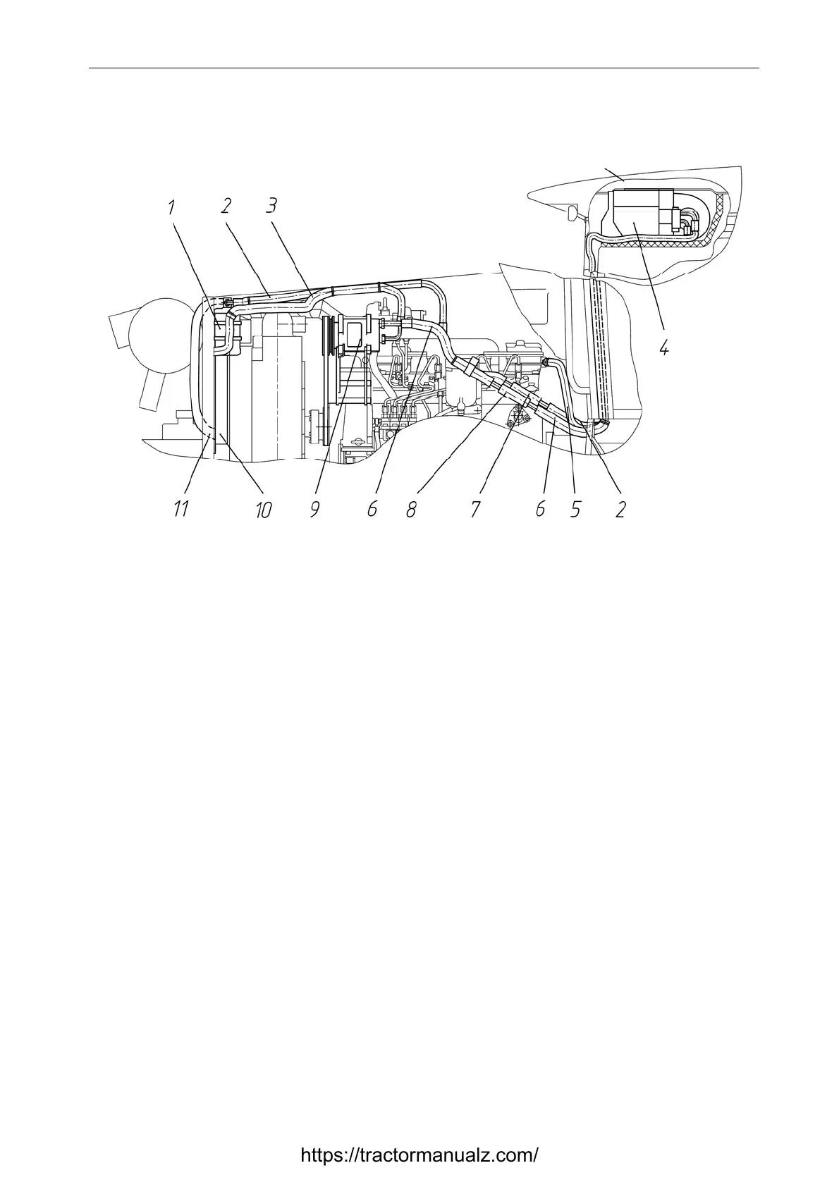
1 - filter drain; 2 - refrigerating fluid delivery line from filter drain to cooler-heater;
3 - refrigerating fluid delivery line from compressor to condenser; 4 - cooler-heater; 5 - refrigerat-
ing fluid delivery line from engine cooling system to cooler-heater; 6 - refrigerating fluid delivery
line from heater-cooler to compressor; 7 - quick-release hoses coupling between a cab and filter
drain; 8- quick-release hoses coupling between a cab and a compressor; 9 - compressor; 10 - con-
denser; 11 - refrigerating fluid delivery line from condenser to filter drain;
Figure 2.12 – Arrangement of main elements of cab
air conditioning and heating system
The climate system starts operating in the air conditioning mode with the engine running,
when the desired fan speed is set with the switch 1 (Figure 2.10), and the switch 2(Figure 2.10) is set
to the beginning of the blue scale.
At that, voltage is supplied to the electromagnetic coupling of the compressor through the con-
trol circuit. The coupling is engaged transferring rotation from the engine crankshaft pulley to the
compressor shaft. The compressor pumps the refrigerating fluid through the elements of the air condi-
tioning system. At that the refrigerating fluid absorbs heat from the air passing through the cooler-
heater, and then releasing heat to the environment through the condenser.
The air conditioning system can automatically maintain the preset temperature that is set by
turning the switch 2 (Figure 2.10) controlling the thermostat. Turning clockwise will decrease the
temperature setting, turning counterclockwise will increase it. Protection from critical conditions is
ensured by the pressure sensor and the thermostat. The sensor turns off the system when the pressure
is too high (over 2.6±0.2 MPa) or too low (below 0.21±0.03 MPa) pressure. The thermostat turns off
the system when the temperature of the cooling section of the heat exchanger unit drops too low. Per-
formance of the system is adjusted by the fan speed and the thermostat. The compressor can operate at
that both continuously and cyclically.
Table 5 presents main parameters and characteristics of the cab air conditioning and heating
system.
Tractor cab roof
https://tractormanualz.com/