BELARUS-920.4/952.4 Operating manual
49
Annex A
(informative)
Electric circuit diagram
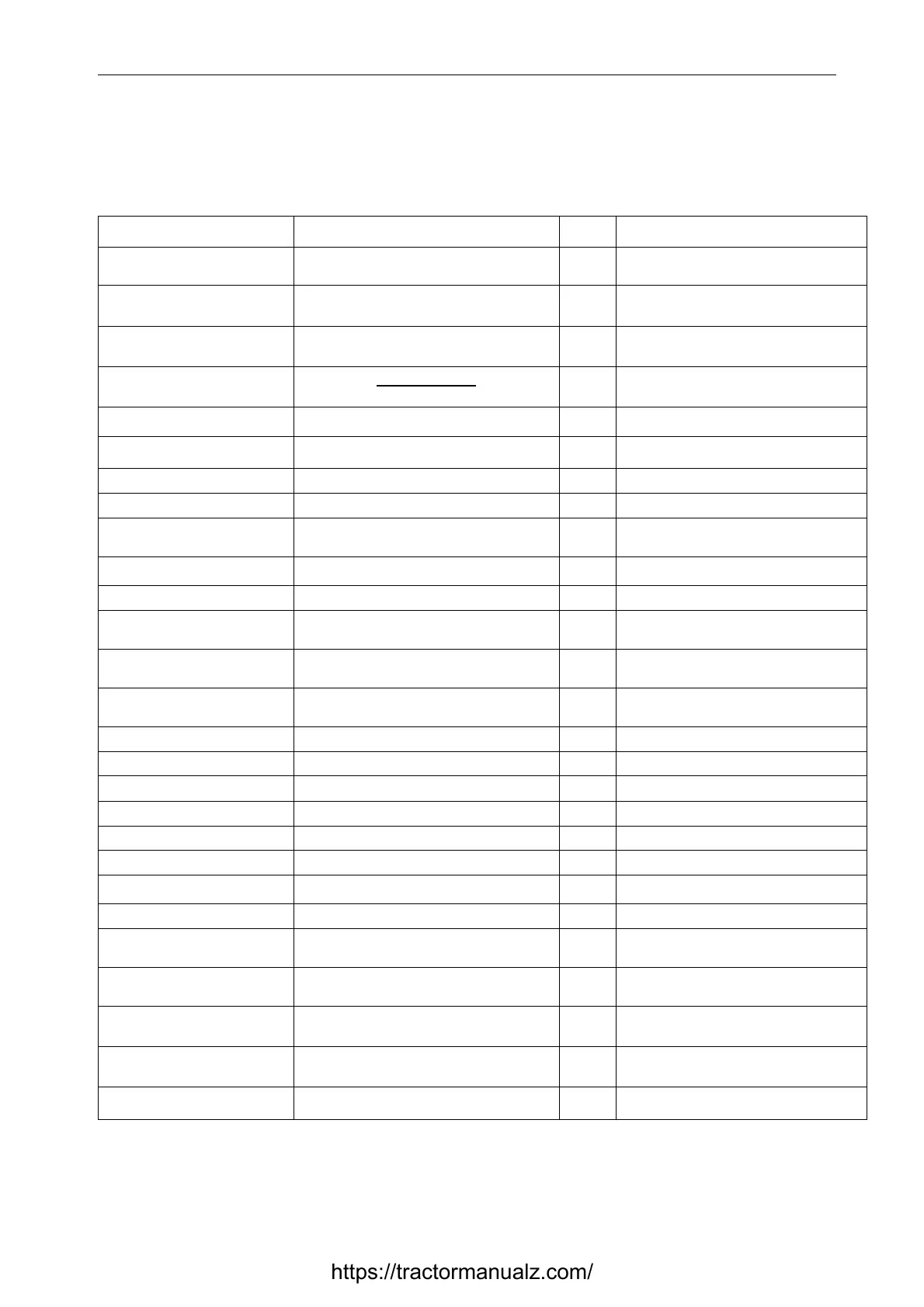
Table A.1 lists items of the electric circuit diagram presented on Figure A.1.
Table A.1
Designation Name Qty. Note
A1 Cassette radio recorder 1
А2 Spark plugs 6 Supplied with engine
For 920.4/952.4/1025.4 — 4 pcs.
A3 Control panel with tachome-
ter/speedometer (with CAN)
1
А4
Air conditioner
1
А4.1 Air processing unit 1 Supplied with conditioner
А4.1.1 Output air temperature regulator 1 Supplied with conditioner
А4.2 Compressor-condenser unit 1 Supplied with conditioner
А4.3 Pressure sensor unit 1 Supplied with conditioner
М7 Fan electric motor 1 Supplied with conditioner
S1 Fan mode selector 1 Supplied with conditioner
ВА1, ВА2 Loud speaker 2 Supplied with radio cassette recorder
BN1 Fuel volume sensor 1
ВР1 Pneumatic system air pressure indicator 1
ВР2 Gearbox oil pressure sensor 1 For 1025.4/1221.4
BV1, BV3 Speed sensor 2
BV2 PTO speed sensor 1 For 1221.4 with PTO speed sensor
Е1, Е2 Road headlight 2
Е3, Е4, Е6, Е7 Working headlight 4
Е5 Interior lamp 1
Е8 Number plate light 1
EL1, EL2 Lamp AKG12-60+55-1 2 Included into Е1, Е2
EL3, EL4, EL13, EL14 Lamp AKG12-55-1 4 Included into Е3, Е4, Е6, Е7
EL5…EL7, EL9, EL10, EL18,
EL19
Lamp A12-5 7 Included into HL1…HL5, E8
EL8, EL11, EL12, EL15,
EL17, EL20, EL22
Lamp A12-21-3 7 Included into HL4, HL5, E5, HL6,HL7
EL16, EL21 Lamp A12-10 2 Included into HL6, HL7
https://tractormanualz.com/