18
V4. 12. 2010
.
Subject to modification
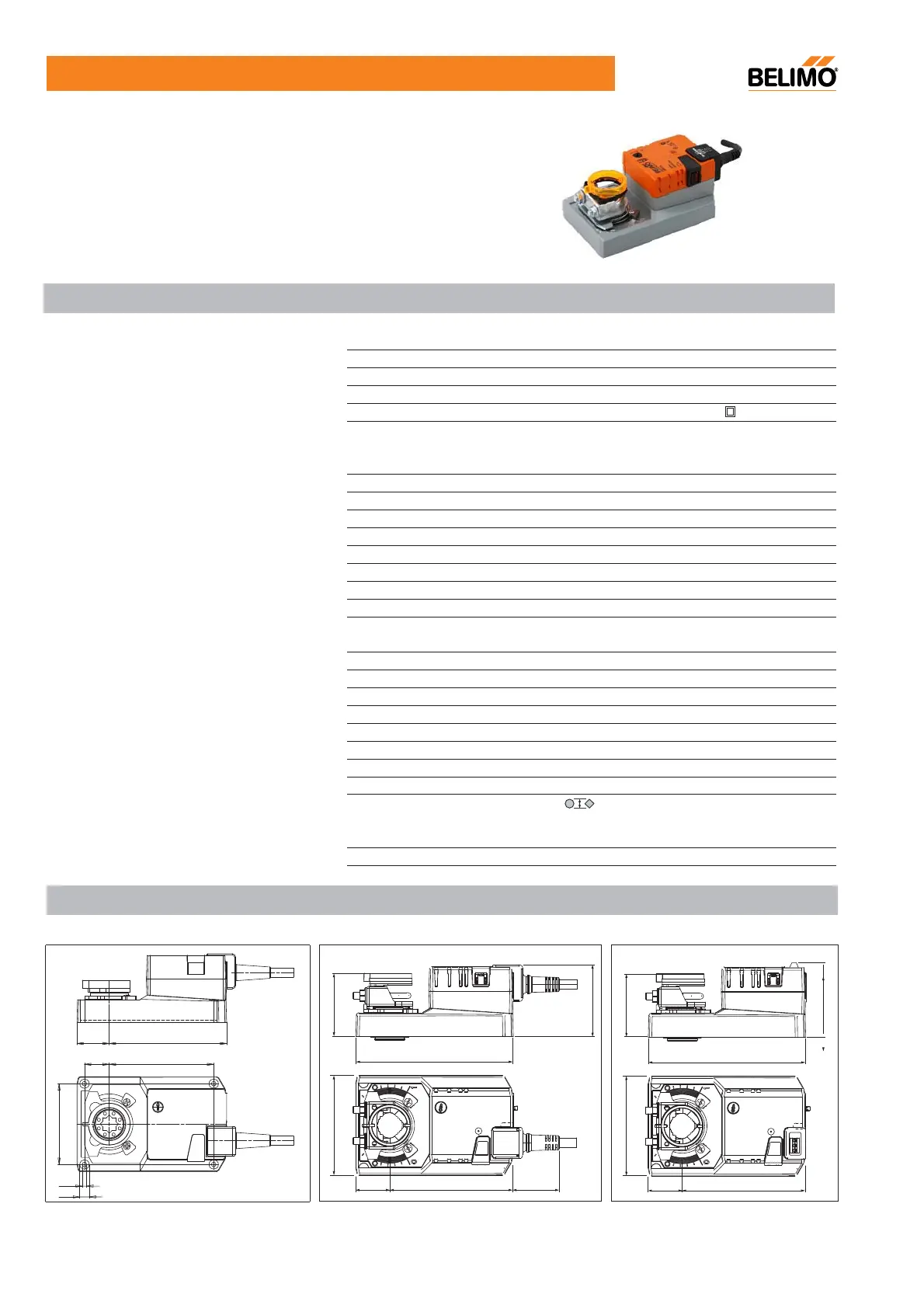
SMU24(-S/-F/-T)
Technical data
Electrical data
AC 24V 50/60Hz, DC 24V
AC/DC 19.2...28.8V
2W @ running / 0.2W @ holding
4VA
Cable 1m, 3x0.75mm
2
Functional data
20Nm
Selectable by switch
Max. 95
°
, adjustable by mechanical stops
150s for 95
°
Max. 48dB(A)
Mechanical, remote visible
Working conditions
III (safety low voltage)
IP54 in any direction
IP20
CE according to 89/336/EEC
Type 1 to EN 60730-1
-30...+50
°
C
-40...+80
°
C
95% RH, non-condensing (EN 60730-1)
Maintenance-free
Dimensions / weight
See 'Dimensions'
12x12mm
Min. 42mm (20mm for reverse mounting)
10...20mm
Approximately 1050g
Dimensions [mm]
Cable 1m, 3x0.75mm
2
Terminals SMU24-T
Max. 3x1.5mm
2
1 SPDT, 1mA...3(0.5)A, AC 250V , adjustable
139
65
6
.76
30
109
88
139
6
5
46
30
109
41
88
SMU24(-S) SMU24-T
SMU24-F
109
30
97
23
4.2
8.8
57
Gearing latch disengaged by pushbutton, self-resetting
(10...26.7mm with K-ENSA - optional)
Nominal voltage
Nominal voltage range
Power consumption
Wire/transformer sizing
Auxiliary switch
SMU24-S
Connection : Motor
Auxiliary switch SMU24-S
Direction of rotation
Torque
Manual override
Angle of rotation
Running time
Sound power level
Position indication
Protection class
Degree of protection: SMU24(-S/-F)
SMU24-T
Ambient temperature
Mode of operation
EMC
Maintenance
Weight
Non-operation temperature
Humidity test
Shaft length
Dimensions (LxWxH)
SMU24-F
Shaft: SMU24(-S)
•ΓFor operation of air control dampers in HVAC system
•ΓTorque: 20Nm
•ΓNominal voltage: AC/DC 24V
•ΓControl: Open/Close or 3-point