LMC24 (-SR) (-T) US
Non-spring return, direct coupled, 24 V, 25 to 35 sec. running time
LMC24… - Typical Specification:
Control damper actuators shall be electronic direct coupled
type which require no crank arm and linkage. Actuators shall
be UL and CSA listed, have a 5 year warranty, and be man-
ufactured under ISO 9001 International Quality Control
Standards. Actuators shall have reversing switch and manual
override on the cover, and be protected from overload at all
angles of rotation. Actuator shall have a nominal running time
of 30 seconds for 95° rotation. Proportional actuators shall
respond to 2 to 10VDC output relative to position regardless of
the amount of damper rotation. A 2 to 10 VDC feedback sig-
nal shall be provided for position indication or master-slave
applications. An electronic angle of rotation adjustment
(LMC24-SR US only) shall be provided to reduce the actuators
rotation from 100 to 20% while still using the full input signal
and feedback control range. Actuators shall be as manufac-
tured by Belimo.
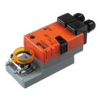
On-off control
3
2
4
5
6
1
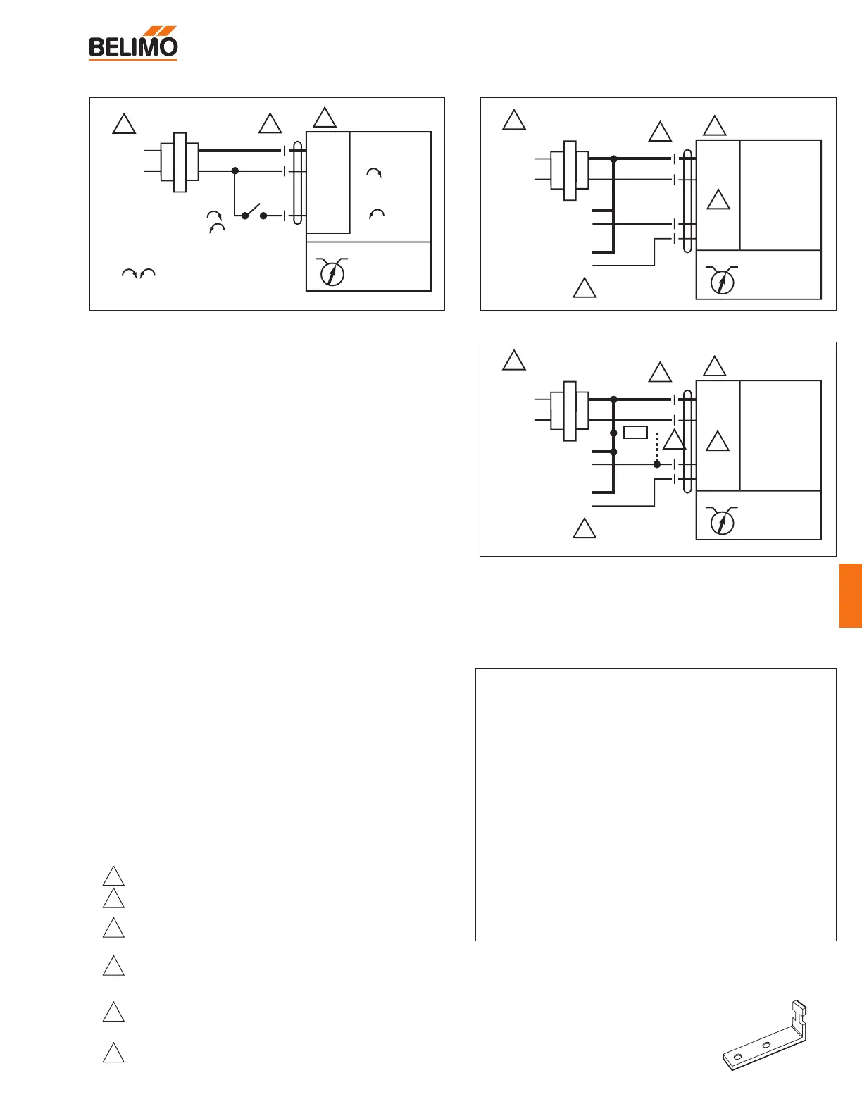
Provide overload protection and disconnect as required.
Actuators may also be powered by 24 VDC
Actuators are provided with color coded wires. Wire
numbers are provided for reference.
Connect actuator common (Wire 1) to Negative (–) leg
of control circuits only.
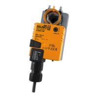
A 500Ω resistor (ZG-R01) must be added for 4 to 20 mA
control.
LMC24-SR-T US does not have a cable. Numbers
shown are terminal numbers.
L-Type anti-rotation bracket. Included with
each actuator.
Part #: 22065