LM
167
G20492-Subject to change. © Belimo Aircontrols (USA), Inc.
®
500Ω
Ω
2 to 10 VDC
Control Signal
(–)
(+)
Blk (1) Common
Red
(2) + Hot
Wht (3) Y
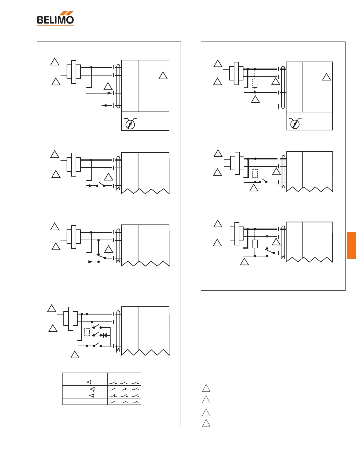
1
Input, 2 to 10V
A Open = 0 V Position
A Closed = Normal Operation
Line
Volts
24 VAC Transformer
2
1
3
Override to zero position
A
Blk (1) Common
Red
(2) + Hot
Wht
(3) Y
1
Input, 2 to 10V
Grn (5) U Output, 2 to 10V
2 to 10 VDC
2 to 10 VDC Feedback Signal
Control Signal
(–)
Line
Volts
24 VAC Transformer
2
1
3
3
Standard Wiring
CCW CW
(+)
Blk (1) Common
Red
(2) + Hot
Wht
(3) Y
1
Input, 2 to 10V
B Closed = 10 V Position
C Closed = Normal Operation
Control Signal
(–)
Line
Volts
24 VAC Transformer
2
1
3
Override to 10 V position
B
C
2 to 10 VDC
(+)
Blk (1) Common
Red
(2) + Hot
Wht
(3) Y
1
Input, 2 to 10V
Control Signal
(–)
Line
Volts
24 VAC Transformer
1
4
3
Override control to min, mid, max, positions
B
C
A
Functions
0%
50%
100%
Control mode acc. to Y
Min*
Mid*
Max*
Normal**
* Default selectable 0-100%. See Configuration Data Sheet.
** Customizable. See Configuration Data Sheet.
abc
(+)
1/4 watt
4 to 20 mA
2-10 VDC or
LM24-MFT US
4
Blk
(1) Common
Red
(2) + Hot
Wht (3) Y
1
Input, 2 to 10V
Grn (5) U Output, 2 to 10V
4 to 20 mA
Control Signal
Line
Volts
24 VAC Transformer
2
1
3
3
Standard Wiring
CCW CW
(+)
(–)
Ω
500Ω
1/4 watt
4 to 20 mA
(–)
Control Signal
(+)
Blk (1) Common
Red
(2) + Hot
Wht
(3) Y
1
Input, 2 to 10V
A Open = 4 mA Position
A Closed = Normal Operation
Line
Volts
24 VAC Transformer
2
4
1
3
Override to zero position
A
Ω
500Ω
1/4 watt
4 to 20 mA
(–)
Control Signal
(+)
Blk (1) Common
Red
(2) + Hot
Wht
(3) Y
1
Input, 2 to 10V
B Closed = 20 mA Position
C Closed = Normal Operation
Line
Volts
24 VAC Transformer
2
4
1
3
Override to 20 mA position
B
Ω
500Ω
1/4 watt
C
2 to 10 VDC Feedback Signal
With a 4-20 mA Input, up to 4 actuators may
be wired in parallel. A 2% shift in the signal
is seen when using a 500Ω resistor. Power
consumption must be observed.
LM24-MFT US
4 to 20 mA Control Signal
Notes
2
3
1
Provide overload protection and disconnect as required.
Actuators may be connected in parallel if not mechanically
mounted to the same shaft. Power consumption and input
impedance must be observed.
Actuator may also be powered by 24 VDC.
ZG-R01 may be used.
4
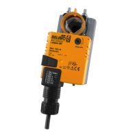
LM24-MFT US
Proportional damper actuator, non-spring return, Multi-Function Technology
®
2 to 10 VDC Control Signal
W038
W039