benchmarkwireline.com
P. O. BOX 850
Fax: 281.342.4848
Phone: 281.342.6415
Simonton,Texas 77476
36220 FM 1093
AM5K User Manual Rev Q Oct 2007 Page 15 of 44
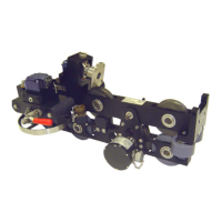
4.4 ASSEMBLY / DISASSEMBLY PROCEDURES
4.4.1 MEASURING WHEEL, SHAFT, AND BEARING REMOVAL
Either measuring wheel can be removed from the measuring head. First shift the
red release handle to move the wheel away from the frame. Next remove the
encoder with its adapter.
On the later model heads, the wheels are keyed onto the shaft and can be
removed simply by removing the screw holding the wheel to the shaft.
On earlier model heads, the wheels are pressed on to the shaft. The lower snap
ring between the wheel and the bearing must first be removed. Pull the wheel
and shaft from the mount. Reassemble in the opposite order. The bearing
should also be replaced at this time.
4.4.2 ELECTRONIC LOAD PIN REMOVAL
The electronic load pin is held in place by one retaining ring on the outer end of
its shaft. Remove the retaining ring by using a small screw driver to lift one end
of the ring out of the groove then “walk” the ring off of the pin. The load pin can
then be removed from the mounting frame.
4.4.3 BACKUP DEPTH MAGNETIC PICKUP REMOVAL AND INSTALLATION
The backup depth magnetic pickup is mounted to the encoder adapter. It is held
in place by four screws. Remove the screws and the pickup can then be
removed. The pickup must be properly oriented to work correctly. The slot
should be oriented to the top. The top side is the encoder side. Ensure that an
o-ring is inserted between the plastic housing and the mount. An additional o-
ring is used between the connector and the housing to keep moisture out.
If the backup display is counting backward (i.e. counting negative when going
down hole), simply rotate the pickup 180 degrees to change the direction.
 Loading...