17
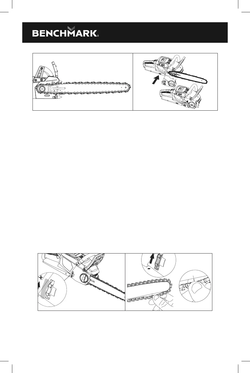
FIG. 12 FIG. 13
NOTE: Small directional arrows are engraved in the saw chain. Another directional
arrow is molded into the housing. When looping the saw chain onto the sprocket,
make sure that the direction of the arrows on the saw chain will correspond to the
direction of the arrow on the housing. If they face in opposite directions, turn over
the saw chain and guide bar assembly.
7. Replace the side cover and slightly tighten the side cover knob (Fig. 13).
8. Lift the tip of the guide bar up to check for sag. Release the tip of the guide
bar and turn the chain tensioning knob clockwise. Repeat this process until
the sag is eliminated.
9. Tighten the side cover knob securely to ensure that the saw chain is properly
tensioned before using.
NOTE: If chain is too tight, it will not rotate. Loosen the side cover knob slightly and
turn the tensioning knob once from right to left. Lift the tip of the guide bar up and
retighten the side cover knob securely. Assure that the chain will rotate without
binding.
Adjusting the chain tension
• Stop the motor and remove the battery pack before adjusting the chain tension.
Make sure the side cover knob is loosened. Turn the chain tensioning knob
clockwise to tension the chain (Fig. 14)
+
0.08" (2 mm)
-
FIG. 14 FIG. 15
• A cold chain is correctly tensioned when there is no slack on the underside of
the guide bar and the chain is snug, but it can be turned by hand without binding.
The chain must be re-tensioned whenever the flats on the drive links do not sit
in the bar groove.