3
TBP202007deen / 10.2012
MK2418
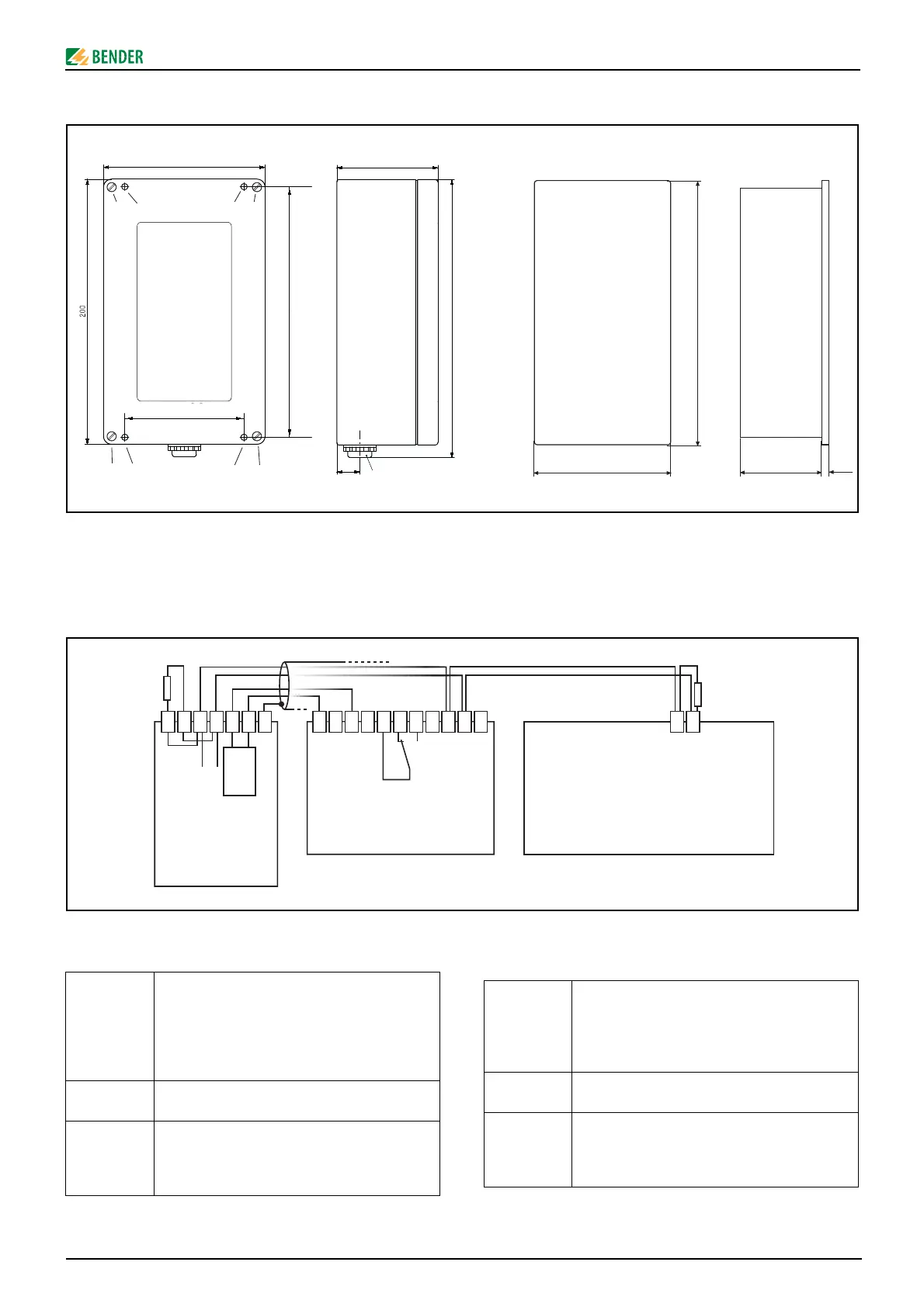
Dimension diagram
All dimensions in mm;
A = Mounting holes; B = Front cover fixing;
MK2418 and MK2418K: switchboard cut-out 160 x 75 mm
Connection
Connection via BMS bus
MK2418-12 displays messages of Medics® systems
Legend to wiring diagram
Devices uti-
lizing a BMS
bus
The BMS bus allows the connection of diffe-
rent Bender devices. These may be, for
example: ISOMETER 107TD47, control and
indicating device s PRC487, residual current
evaluators RCMS470 and others.
AN450 Additional transformer to supply a maximum
of 3 MK2418
R When two or more devices are connected via
the BMS bus, the bus must be terminated with
resistors (R= 120 Ω) at the beginning and the
end.
Maßbild
Alle Maße in mm;
A = Befestigungsbohrungen; B = Deckelbefestigung;
MK2418 und MK2418K: Schalttafelausbruch 160 x 75 mm
Anschluss
Anschluss über BMS-Bus
MK2418-12 zeigt Meldungen von Medics®-Systemen an.
Legende zum Anschlussschaltbild
Geräte mit
BMS-Bus:
Hier können über den BMS-Bus verschiedene
Bender-Geräte mit BMS-Bus angeschlossen
werden. Dies können zum Beispiel sein: ISO-
METER 107TD47, Steuergeräte PRC487, Diffe-
renzstrom-Auswertegeräte RCMS470 und
viele mehr.
AN450 Zusatztransformator für die Versorgung von
max. 3 MK2418
R Werden zwei oder mehrere Geräte über den
BMS-Bus verbunden, so müssen Anfang und
Ende des Busses mit je einem Widerstand (R=
120 Ω) abgeschlossen werden.
88
188
AA
AA
B
BB
B
85
170
54 5
120
75
PG 13,5
17
209,5
31
32
32
31
33
34
PE
V2
V2
U2
U2
11
12
14
A
B
R
U2
V2
A
B
AN450
MEDICS
®
-System
UMC
USC
UFC
LFC
LTIC
BMS-Bus
MK2418-12
Sammelmeldung
Common alarm
BMS-Bus
A
B
weitere Geräte mit BMS-Bus (Option)
further devices with BMS bus (option)
R