2
TBP202007deen / 10.2012
MK2418
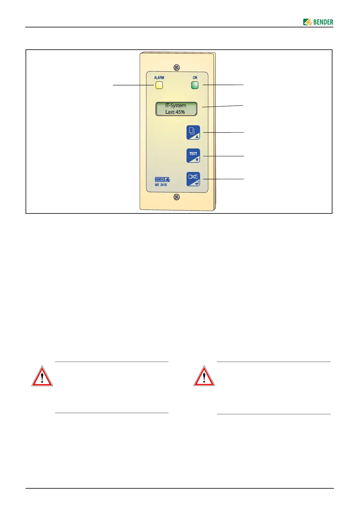
Operating elements
1 "ALARM" LED (yellow) lights when a fault has been de-
tected and keeps lighting until the error is eliminated.
2 LED "ON" (green) lights up when the device is in opera-
tion.
3 Illuminated text display (2 x 16 characters)
4 In the display mode: additional information respec-
tively switching to English language.
In the Menu mode: arrow key for navigation within the
menus and for changing parameters.
5 In the display mode: "TEST" button for testing the insu-
lation monitoring device.
In the Menu mode: arrow key for navigation within the
menus and for changing parameters.
6 In the display mode: "Buzzer off" button. The buzzer
sounds again in on the occurrence of a new alarm mes-
sage.
In the Menu mode: ENTER key to confirm the selected
menu items or to confirm the selected parameters.
Installation and connection
Installation
The MK2418 is available in several versions for flush-mounting,
surface mounting and cable-duct mounting (refer to ordering de-
tails).
Prior to installation and before work activities are
carried out on the connecting cables, make sure
that the mains power is disconnected.
Failure to comply with this safety information
may personnel expose to electric shock. Further-
more, substantial damage to the electrical instal-
lation and destruction of the device can occur.
Bedienelemente
1 LED „ALARM“ (gelb) leuchtet wenn ein Fehler erkannt
wurde. Sie verlöscht erst, wenn Fehler beseitigt ist.
2 LED „ON“ (grün) leuchtet, wenn Gerät im Betrieb ist.
3 Beleuchtete Text-Anzeige (2 x 16 Zeichen)
4 Im Anzeige-Modus: Zusatzinformation bzw. Sprachum-
schaltung Englisch,
Im Menü-Modus: Pfeiltaste zur Navigation innerhalb
der Menüs und zum Ändern von Parametern.
5 Im Anzeige-Modus: Taste „TEST“ zum Prüfen des Isolati-
onsüberwachungsgerätes,
Im Menü-Modus: Pfeiltaste zur Navigation innerhalb
der Menüs und zum Ändern von Parametern.
6 Im Anzeige-Modus: Taste „Summer aus“. Der Summer
ertönt erneut bei Auftreten einer neuen Alarmmel-
dung.
Im Menü-Modus: ENTER-Taste zur Bestätigung der an-
gewählten Menüpunkte bzw. zur Bestätigung der aus-
gewählten Parameter.
Montage und Anschluss
Montage
MK2418 ist in verschiedenen Versionen für Montage Unterputz,
Aufputz oder in Wandkanälen erhältlich (siehe Bestellangaben).
Stellen Sie vor Einbau des Gerätes und vor Arbei-
ten an den Anschlüssen des Gerätes sicher, dass
die Anlage spannungsfrei ist.
Wird dies nicht beachtet, so besteht für das Perso-
nal die Gefahr eines elektrischen Schlages.
Außerdem drohen Sachschäden an der elektri-
schen Anlage und die Zerstörung des Gerätes.