4
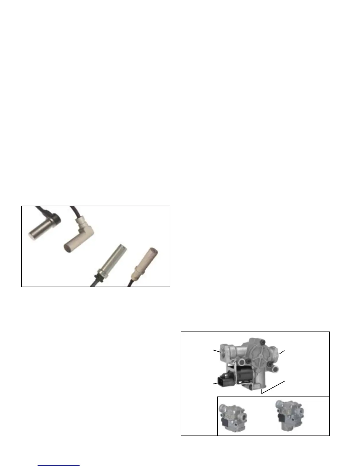
FIGURE 5 - BENDIX
®
WS-20
™
AND WS-24
™
WHEEL SPEED
SENSORS
EC-30
™
CONTROLLER INPUTS
Power and Ground
Power is supplied to the EC-30
™
controller from the ignition
circuit through a 30 Amp fuse. The EC-30
™
controller is
grounded to the vehicle chassis. For EC-30
™
controller power
and ground connector pin locations, see EC-30
™
controller
system schematic, Figure 14.
Wheel Speed Sensors
Wheel speed data is provided to the EC-30
™
controller from
the Bendix
®
WS-20
™
or WS-24
™
wheel speed sensors. See
figure 5 for wheel speed sensor illustrations. Working with
an exciter ring, wheel speed sensors provide the EC-30
™
controller with an AC signal, which varies in voltage and
frequency in relation to the speed of the wheel. The EC-30
™
controller can be configured to receive wheel speed
information from 100 or 86 tooth exciter rings. Vehicle axle
configurations and ATC features determine the number of
speed sensors that must be used. A vehicle with a single
rear drive axle (4x2, 4x4 or 6x2) requires four speed sensors
for both ABS and ATC operation. A vehicle with two rear
drive axles (6x4) can utilize six speed sensors for optimal
ABS and ATC performance. For wheel speed sensor
connector pin locations, see the EC-30
™
controller system
schematic, Figure 14.
Blink Code Switch
The EC-30
™
controller can be configured to support an
optional diagnostic blink code switch to ground, which can
be used to activate several functions available through blink
code diagnostics. Pin F3, of the 30-pin connector, is the
blink code switch input.
Three Position Switch for ATC and Blink Codes
The EC-30
™
controller can be configured to receive both the
ATC enable/disable signal and the blink code activation signal
from a single three-position switch. In this case, the common
position of the switch is connected to pin F2 of the 30-pin
connector. The normally-open switch position is connected
to +12 VDC to disable ATC. The normally-open (momentary)
switch position is connected to ground to activate blink codes.
When configured in this manner, there is no wire installed in
pin F3 of the 30-pin connector, which is normally used for
the blink code switch input.
Brake Switch Input
The EC-30
™
controller can be configured to support an
optional brake switch input. The brake switch input can be
used in accordance with ABS and ATC performance. Pin
A2, of the 18-pin connector, is the brake switch input.
EC-30
™
CONTROLLER OUTPUTS
ABS Modulators
Bendix
®
ABS modulators (M-21
™
, M-22
™
, M-30
™
or M-32
™
)
are controlled by the EC-30
™
controller to modify driver
applied air pressure to the service brakes during ABS or
ATC activation. See figure 6 for illustration. The ABS
modulator, an electro-pneumatic control valve, is the last
valve that air passes through on its way to the brake chamber.
The modulator hold and exhaust solenoids are activated to
precisely modify the brake pressure during ABS. The hold
solenoid is normally open and the exhaust solenoid is
normally closed. The EC-30
™
controller is able to control
four individual modulator assemblies. For ABS modulator
connector pin locations see the EC-30
™
controller system
schematic, figure 13.
ATC Enable/Disable Switch
Premium EC-30
™
controller models, configured for ATC,
monitor an ATC enable/disable switch to +12 VDC, which
allows ATC to be manually deactivated. The ATC active/
warning lamp will be on while the ATC is disabled. Pin F2,
of the 30-pin connector is the ATC enable/disable switch
input.
J1939 - ATC Enable/Disable Switch
The EC-30
™
controller can be configured to receive the status
of the ATC enable/disable switch over the SAE J1939 serial
communications link. A vehicle controller will monitor the
position of the ATC enable/disable switch directly, and
broadcast a J1939 message indicating its status. When
configured in this manner, there will be no wire installed in
pin F2 of the 30-pin ECU connector. In the event that J1939
communications is lost between the EC-30
™
controller and
the vehicle controller, the EC-30
™
controller will disable the
ATC function.
90° Speed
Sensors
Straight Speed
Sensors
WS-24
™
Sensor
WS-20
™
Sensor
WS-20
™
Sensor
WS-24
™
Sensor
FIGURE 6 - M-30
™
, M-32
™
, AND M-32QR
™
MODULATORS
Delivery
(Port 2)
Supply
(Port 1)
Exhaust
(Port 3)
Electrical
Connector
M-30
™
Modulator
M-32QR
™
Modulator
M-32
™
Modulator