6
CHART 4 - LED POWER-UP DISPLAY OF EC-30
™
CONTROLLER CONFIGURATION
LED Power-Up Sequence LEDs
1
st
When power is applied All LEDs Illuminate
Then the LEDs indicate one of the following:
2
nd
4 Sensors SEN-RER-FRT
6 Sensors SEN-RER-MID-FRT
Then the LEDs indicate one of the following:
ATC Engine Limiting TRC
3
RD
ATC Differential Braking TRC-MOD
No ATC N/A
The LEDs will then indicate system status:
4
th
Normal Operation (if no faults) VLT
POWER-UP SEQUENCE
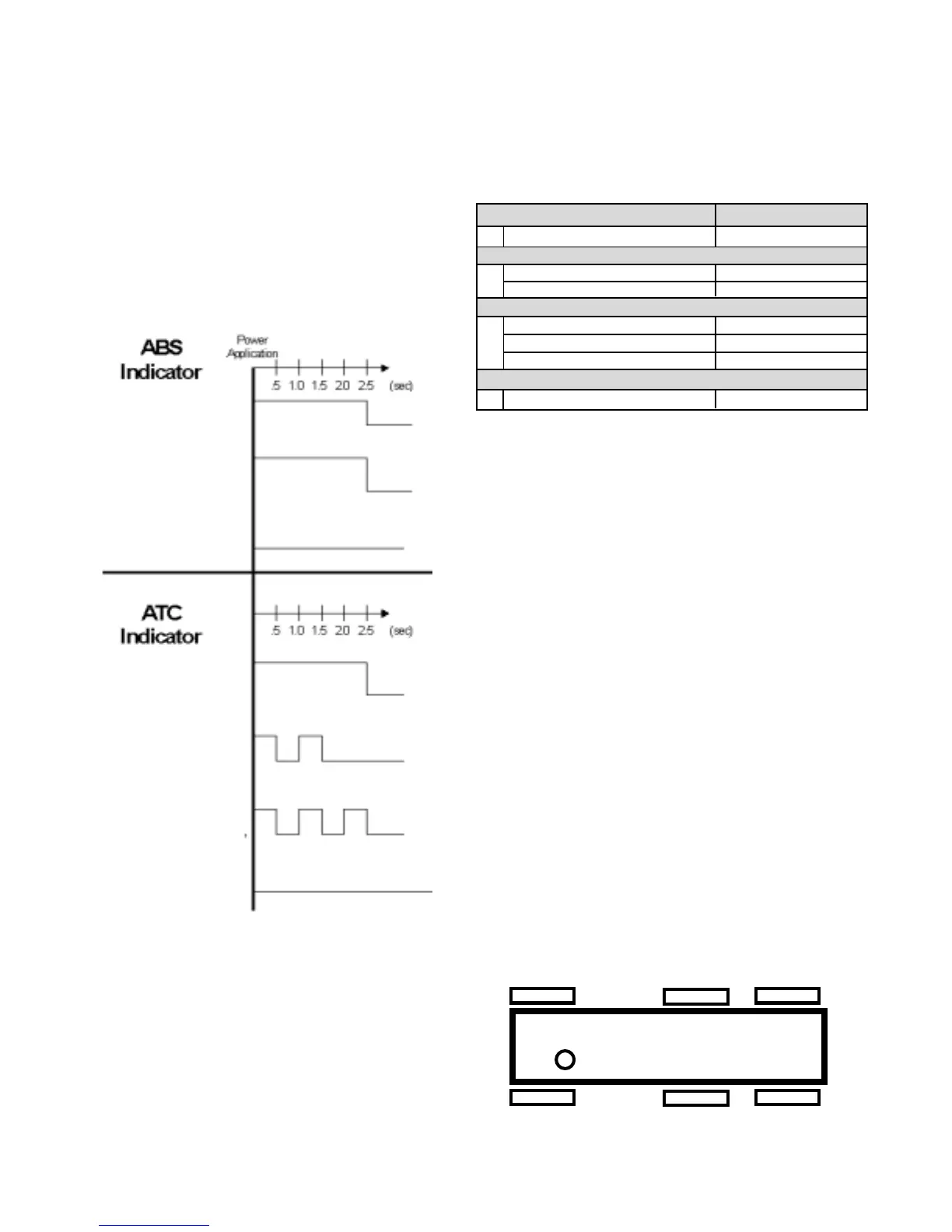
ABS Warning Lamp at Power-Up
At power-up without detected faults, the ABS warning lamp
turns on for 2.5 seconds and then turns off. See figure 7.
ATC Active / Warning Lamp at Power-Up
At power-up, the ATC active/warning lamp displays the ATC
control configuration and then turns off. A series of blinks
indicates if the ATC is configured for engine torque limiting
and differential braking, engine torque limiting only, or
differential braking only. See figure 7.
Driver
Right Front
Left Front
Right Rear
Left Rear
Right Mid
Left Mid
FIGURE 8 - VEHICLE ORIENTATION
FIGURE 7 - EC-30
™
CONTROLLER POWER-UP LAMP
SEQUENCE
Diagnostic LEDs at Power-Up
At power-up, the diagnostic LEDs all turn on, then display
the configuration for sensors and the ATC. After showing
the configuration, only the green VLT LED will stay on.
However, if a fault is detected, the faulted component will be
identified by the red LEDs. See chart 4.
Retarder Disable Relay at Power-Up
At power-up, the EC-30
™
controller may toggle the retarder
disable relay. If the relay is located in the cab it is usually
audible to the operator.
Modulator Chuff Test at Power-Up
At power-up, the EC-30
™
controller activates a patented
modulator chuff test. The modulator chuff test is an electrical
and pneumatic ABS modulator test, that can assist the
technician in verifying proper modulator wiring and installation.
With brake pressure applied, a properly installed modulator
causes a single sharp audible chuff of air pressure by
activating the hold solenoid two times and the exhaust
solenoid once. If the modulator is wired incorrectly, the
modulator will produce a double chuff, or no chuff at all. The
EC-30
™
controller activates a chuff at each modulator in the
following sequence:
Right-Front, Left-Front, Right-Rear, Left-Rear. See figure 8.
The chuff sequence is then repeated for a total of 8 chuffs. If
an issue is detected during the modulator chuff test, look
for faults and compare the modulator wiring and plumbing to
the EC-30
™
controller system schematic shown in figure 13.
Trailer ABS WL
(PLC Detected)
Trailer ABS WL
(PLC Not Detected)
ON
OFF
Powered Vehicle ABS WL
ON
OFF
ON
Engine torque
limiting and
differential braking
ON
OFF
Engine torque
limiting only
ON
OFF
Differential braking only
ON
OFF
No ATC
OFF
ON
OFF
Trailer ABS Warning Lamp
At power-up, the trailer ABS warning lamp turns on for 2.5
seconds and then turns off. This only occurs if a PLC trailer
or PLC diagnostic tool is connected to the tractor at the
time ignition power is applied. Only an EC-30
™
controller
with PLC installed on a towing vehicle will support the trailer
ABS lamp.