30
SECTION K - TROUBLESHOOTING EC-30
™
CONTROLLER
SERIAL COMMUNICATION
For vehicles using J1939, verify
continuity between the 30-pin
connector (pins C3, D2, D3) and the
3-pin engine or dash controller
connector.
For vehicles using J1922, verify wire
continuity between the 30-pin
connector (pins B2, B3) and the 2-pin
engine or dash controller connector.
For vehicles using J1587, verify wire
continuity between the 30-pin
connector (pins G2, G3) and the 2-pin
dash controller connector.
Verify no continuity from serial
communication pins to ground (except
pin D2). Verify +12 VDC is not
measured at any serial communication
pin. Check for corroded or damaged
serial communication wiring and
connections. If a circuit fault is found,
isolate the area needing repair by
repeating the measurements at all
serial communication link connectors.
Make repairs to serial communication
wiring. Reconnect all connectors to
the EC-30
™
controller and engine.
Reset any fault codes by briefly
holding a magnet in place at the
RESET location of the diagnostic
display. Then rerun the power-up
sequence. Go to Sections A and B.
TRC LED and ATC active/warning
lamp are on.
C3 Engine Communication, J1939 H
D3 Engine Communication, J1939 L
D2 Engine Communication, J1939 Shield
B2 Engine Communication, J1922 +
B3 Engine Communication, J1922 -
G2 Diagnostic, J1587, Serial A
G3 Diagnostic, J1587, Serial B
If the EC-30
™
controller has just been
configured or replaced, verify that the
EC-30
™
controller is configured to
operate the warning lamp(s) using the
appropriate serial communications
link. The Bendix ABS Diagnostic
Software program will be needed to
verify this level of configuration. If the
EC-30
™
controller was replaced with
the correct replacement part number,
this step is not necessary.
If the EC-30
™
controller is configured
properly, verify proper operation of the
vehicle dash controller.
Warning lamp(s) controlled by
serial communication link not
functioning properly.
Turn ignition off and remove the 30-pin
connector from the EC-30
™
controller.
Also remove the dash controller
connector.
Turn ignition off and remove the 30-pin
connector from the EC-30
™
controller.
Also remove the 2- or 3-pin connector
at engine controller.
Verify proper operation of the electronic
engine controller.
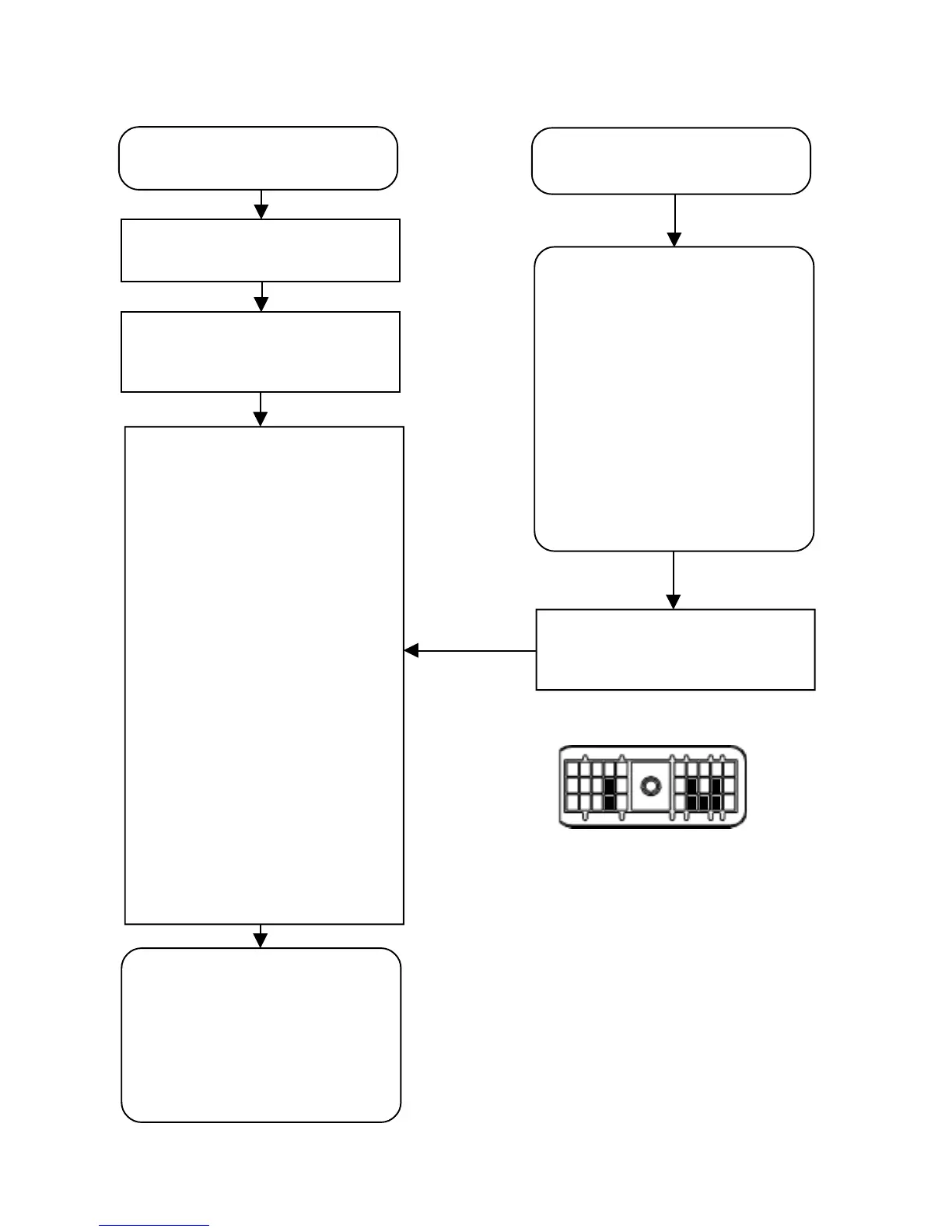
1
2
3
K J H G F E D C B A
30-Pin Connector